
- PolyJet Legacy Printers
- Alaris30 V1
- Connex260
- Connex350/500
- Eden250
- Eden260
- Eden260V/VS
- Eden330
- Eden350
- Eden350V/500V
- J700 & J720 Dental
- J750/J735
- J750 Digital Anatomy
- Objet24/30 V2 Family
- Objet24/30 V3 Family
- Objet30 V5 Pro & Prime
- Objet260 Connex 1-2-3
- Objet260 Dental & Dental Selection
- Objet350/500 Connex 1-2-3
- Objet1000 Plus
- PolyJet Materials
- Agilus30 family
- Biocompatible
- Biocompatible Clear MED610
- Dental Materials
- Dental TrueDent Materials
- Dental TrueDent-D Materials
- Digital ABS Plus
- DraftGrey
- Elastico Clear/Black
- High Temperature
- MED610-DSG
- PolyJet Support
- Rigur & Durus
- Tango
- PolyJet ToughONE™
- Transparent
- Vero ContactClear
- Vero Family
- Veroflex
- VeroUltra Opaque
- Vivid Colors
- Stereolithography Materials
- Somos® 9120™
- Somos® BioClear™
- Somos® DMX SL™ 100
- Somos® Element™
- Somos® EvoLVe™ 128
- Somos® GP Plus™ 14122
- Somos® Momentum™
- Somos® NeXt™
- Somos® PerFORM™
- Somos® PerFORM Reflect™
- Somos® ProtoGen™ 18420
- Somos® ProtoTherm™ 12120
- Somos® Taurus™
- Somos® WaterClear® Ultra 10122
- Somos® WaterShed® AF
- Somos® WaterShed® Black
- Somos® WaterShed® XC 11122
- Somos® WaterShed® XC+
Wood Grain/Swirl Pattern
Wood Grain/Swirl Pattern on Part Surface
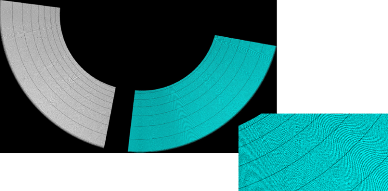
A wood grain or swirl-like pattern may appear on printed models. This is expected behavior and not a print quality defect. This is a sign of a highly calibrated printer.
The severity of the pattern can vary depending on:
- Model orientation
- Geometry (curved vs. flat surfaces)
- Print settings and finishing
Note the following:
- The presence of the pattern on both top and bottom surfaces helps distinguish it from issues such as Z-start errors, which typically affect only the bottom surface.
- The pattern might resemble machining marks, but it is a normal output of the technology.
- Hardware replacements, software reinstallation, or calibration adjustments do not eliminate pixelation-related patterns.
Figure 1: Top view —Left : Pattern; Right: Close-up
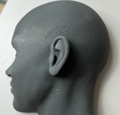
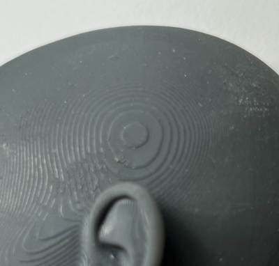
Figure 2: Side view —Left : Pattern; Right: Close-up
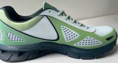

Figure 3: Side view —Left : Pattern; Right: Close-up
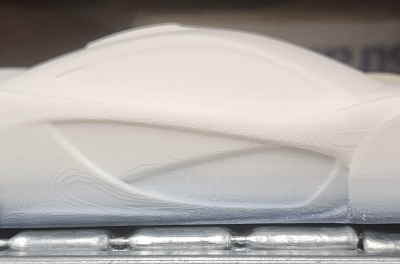
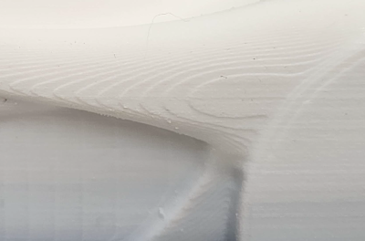
Possible Causes and Solutions
Inherent Pixelization in 3D Printing
On all 3D printing systems, this visual wood grain or swirl pattern texture is caused by a phenomenon known as pixelization.
- This effect is inherent to layer formation (how material is deposited during printing).
- It occurs when pixels are formed by multiple nozzles rather than a single nozzle
- It can be visible on matte and glossy surfaces, both before and after cleaning, and on both top and bottom surfaces. In some cases, it might also appear on model side surfaces.
This pattern does not indicate a system malfunction, calibration issue, or incorrect settings.
Figure 4: Wood grain appearance on glossy surface
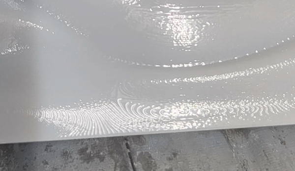
Figure 5: Bottom view wood grain
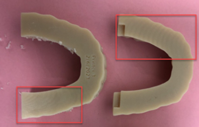
Figure 6: Top view wood grain
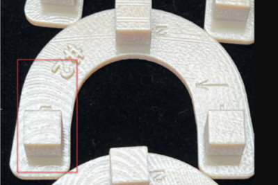
Figure 7: Wood grain appearance along the tray
Solution: If the visual impact is a concern, adjust model orientation by moving the wood grain appearance to a different surface of the model.
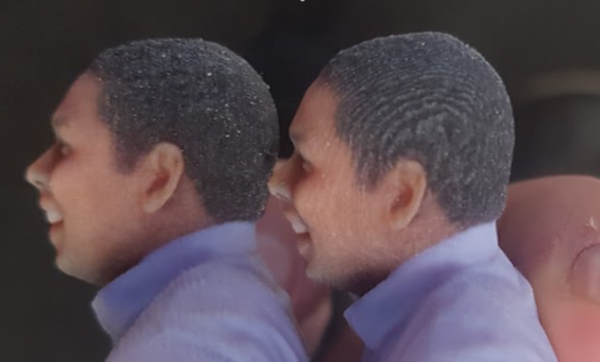
- Rotate the model around the Z-axis during job preparation.
- Reposition the model so critical surfaces are less affected.
Note: Adjusting orientation does not eliminate the pattern. It only changes its direction or location on the model.
Figure 8: Left: Pattern not visible; Right: Pattern visible
Preventive Measures:
- Plan the model orientation in advance to minimize pattern visibility on critical surfaces.
- Position aesthetic or functional surfaces away from dominant pattern directions.
- Set expectations with stakeholders or customers regarding this inherent appearance.