- PolyJet Legacy Printers
- Alaris30 V1
- Connex260
- Connex350/500
- Eden250
- Eden260
- Eden260V/VS
- Eden330
- Eden350
- Eden350V/500V
- J700 & J720 Dental
- J750/J735
- J750 Digital Anatomy
- Objet24/30 V2 Family
- Objet24/30 V3 Family
- Objet30 V5 Pro & Prime
- Objet260 Connex 1-2-3
- Objet260 Dental & Dental Selection
- Objet350/500 Connex 1-2-3
- Objet1000 Plus
- PolyJet Materials
- Agilus30 family
- Biocompatible
- Biocompatible Clear MED610
- Dental Materials
- Dental TrueDent Materials
- Dental TrueDent-D Materials
- Digital ABS Plus
- DraftGrey
- Elastico Clear/Black
- High Temperature
- PolyJet Support
- Rigur & Durus
- Tango
- ToughONE™
- MED610-DSG
- Transparent
- Vero ContactClear
- Vero Family
- Veroflex
- VeroUltra Opaque
- Vivid Colors
- Stereolithography Materials
- Somos® 9120™
- Somos® BioClear™
- Somos® DMX SL™ 100
- Somos® Element™
- Somos® EvoLVe™ 128
- Somos® GP Plus™ 14122
- Somos® Momentum™
- Somos® NeXt™
- Somos® PerFORM™
- Somos® PerFORM Reflect™
- Somos® ProtoGen™ 18420
- Somos® ProtoTherm™ 12120
- Somos® Taurus™
- Somos® WaterClear® Ultra 10122
- Somos® WaterShed® AF
- Somos® WaterShed® Black
- Somos® WaterShed® XC 11122
- Somos® WaterShed® XC+
Preparing a Build for SAF Printers
Rather than being limited to the 2D area of the tray, the H350 can arrange parts in the full 3D volume build area. Because of this, adding models to the build is a two-step process:
- Models are added to the Preparation Area where settings can be adjusted.
- Selected models are then nested into the 3D Nest.

Preparation Area
The preparation area is an infinite 2D plane where models can be added and modified. Models cannot be added directly to the nest, they must first be added to the preparation area.
Use the preparation area to:
- Scale the models and/or select different units for unitless file types
- Perform mesh analysis and repair
- Inspect your model from all sides before adding it to the 3D nest where it may become obscured
To learn more about selecting an orientation for your model for optimum surface finish, please refer to the SAF Design Guide.
When a model is selected, an outline of the build volume is shown in green to give you an idea of the scale of the model. This can be turned off from the view control strip at the top of the screen.
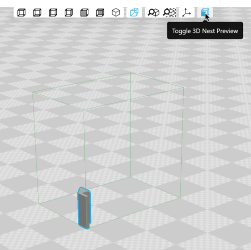
Before models can be nested, they must be checked and repaired using Analysis Mode. A user preference, which is on by default, checks models automatically as they are added. This saves a step but can be resource intensive for complex models. You can disable the preference and check models manually from Analysis Mode. If any models are in need of repair, click Repair All Models.
A number of actions can be performed from either the preparation area or the nest area:
- Duplicate or copy & paste models
- Change the orientation and lock it in one or more axes
- Mirror a model
- Add text to a model’s surface using the labels tool. Learn more here.
Automatic Nesting
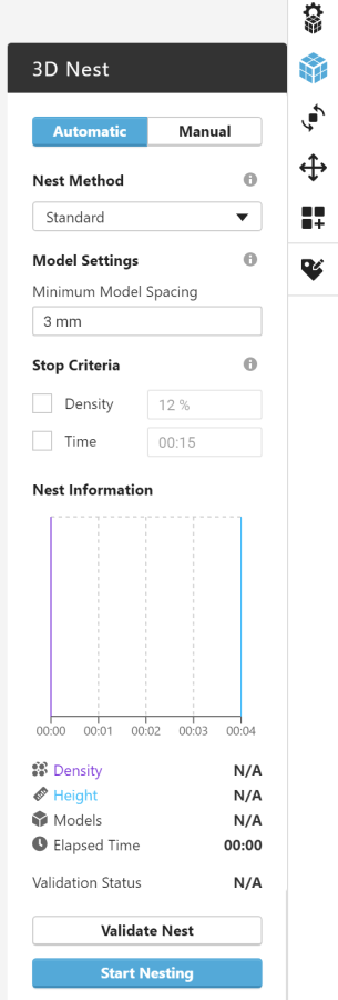
The 3D Nesting panel contains a few controls:
- The nest method may be either standard or advanced.
- Compact may return a denser nest solution but may contain interlocks and take longer to run.
- No Interlocks will always return a nest without interlocks. It may be quicker to run but may be less dense.
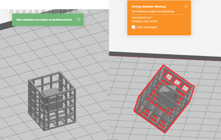
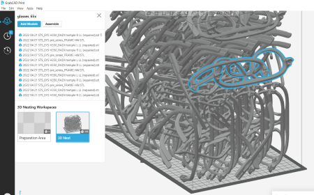
| False Positive | False Negative |
|---|---|
 |
 |
- You can select the minimum spacing between models. When adjusting the minimum spacing, please refer to the SAF Design Guide, but in general, you may want to increase the minimum spacing when printing large parts.
- You can enter a limit on the automatic nesting process called a Stop Criteria. Automatic nesting can take a long time, especially when trying to create a nest that fills the entire build volume or when your models have complex shapes. The Stop Criteria allows you to interrupt the process before it has finished optimizing the nest. The result may not be the shortest print or the densest nest possible, but it avoids having to wait for the full optimization to complete. You can also stop the nesting process manually. The Nest Information section displays the detailed progress of the nesting process, and you can stop the process if the optimization is sufficient for your needs.
To begin automatic nesting, start by selecting the models you want to print. You can use CTRL+A to select everything in the project, or you can click-and-drag in the viewer to box-select multiple models. You can also pick models individually by holding down the CTRL key and click on models in the viewer or in the file list. Only the selected models are nested, and if any models are already in the nest and are not selected, they will be excluded from the nest. These models will appear outside the build volume in the 3D Nest.
Manual Nesting
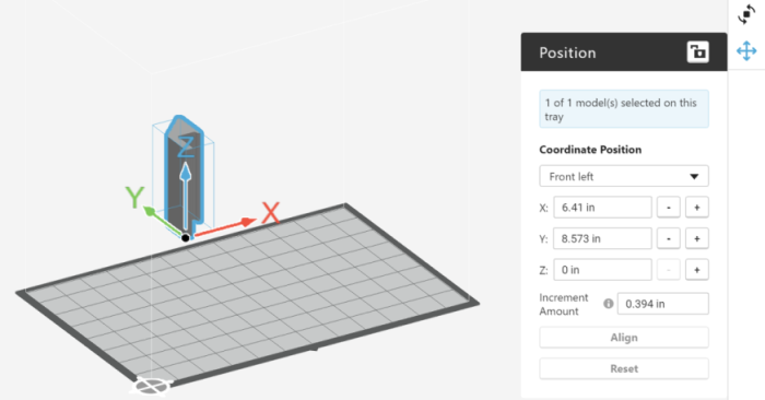
Once a model is in the 3D Nest view, either in the build volume or just outside it, you can manually move or reorient the model using the translation and orientation tools. Enable the 3D manipulator in the view control strip to free drag your model or use the Position tool panel to move the model specific increments.

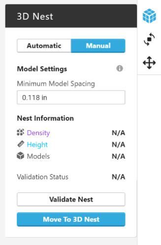
Then in the 3D Nest tool panel, click Validate Nest to ensure that the nest is printable and to recalculate the density and print time.
3D Arrays
Once models are in the nest area, you can create an array of duplicates using the 3D array tool:
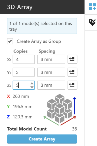
The tool panel allows you to control the size of the array, the direction to grow the array in relation to the original model, as well as the spacing between the models within the array. The Create Array as Group affects how models within the array can be selected. When the array is created as a Group, the array may only be selected as a whole, and operations such as moving, reorienting, or nesting will maintain the arrangement of the array. When you deselect this checkbox, the resulting models in the array are added as individual duplicates and can be selected individually. This will allow you to create arrays around other parts in your build, as you can create an array, then delete any individual models that interfere.
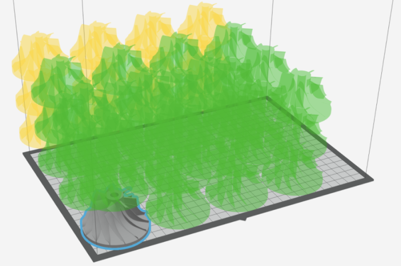
When you are creating an array, a preview is shown. Models that exceed the build volume will be shown in yellow.
Shrinkage Compensation
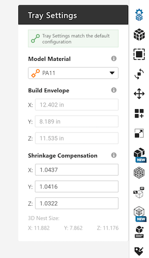
When models are printed on an SAF printer, their dimensions are enlarged before they are sent to the printer, because as the printed model cools, it shrinks. The precise amount that the model is enlarged is called the shrinkage compensation factor. During the printer’s calibration, you determine an exact compensation factor for the X, Y, and Z directions of the build, and when you select your H350 in GrabCAD Print, those factors are copied into the 3D Nest Settings panel. Please refer to your User Guide when setting these values.
How Shrinkage Compensation is Applied
In GrabCAD Print, you will always see measurements in the “cold” state, meaning, after the printing is completed and models have reduced back to their as-designed size. The scale tool shows your models’ measurements as-designed, without compensation factors applied, and the position tool and model spacing option use measurements relative to your model’s true size.
The way GrabCAD Print applies the compensation factors is to the entire nest volume. The dimensions of the H350 build chamber are 315 mm × 208 mm × 293 mm, however the nest volume you see in GrabCAD Print is slightly smaller, 315 ∕ S X × 208 ∕ SY × 293 ∕ SZ, where SX, SY and SZ are the shrinkage compensation factors in X, Y, and Z. The shrinkage compensation factors are applied to the nest as a whole, not to the individual models, which ensures that they don’t interfere with one another or exceed the boundaries of the build chamber.
How density is calculated
“Density” as it relates to the 3D nest refers to the amount of the available build volume that is filled with models for the height of the nest. It can be expressed with the following formula:
![]()
Where S X and SY are the shrinkage compensation factors in X and Y, the build area of the H350 is a constant (315 mm × 208 mm) and the height of the nest is displayed in the Nest Information section of the 3D Nest tool panel. Only the X and Y shrinkage compensation factors are applied in the density calculation because the Z is factored out by the height.
If You’re Coming from Other Software
Other software may apply the shrinkage compensation factors differently and also calculate density differently.
For instance, in Materialise Magics, the full build chamber volume is available for nesting, but models and other measurements are displayed in their “cold” as-designed state, allowing more or larger models into the nest. The compensation factors are then applied during the creation of the build file. The density shown in Magics does not factor in the shrinkage compensation, so given the same nest, it will show a lower value for density.
