- PolyJet Legacy Printers
- Alaris30 V1
- Connex260
- Connex350/500
- Eden250
- Eden260
- Eden260V/VS
- Eden330
- Eden350
- Eden350V/500V
- J700 & J720 Dental
- J750/J735
- J750 Digital Anatomy
- Objet24/30 V2 Family
- Objet24/30 V3 Family
- Objet30 V5 Pro & Prime
- Objet260 Connex 1-2-3
- Objet260 Dental & Dental Selection
- Objet350/500 Connex 1-2-3
- Objet1000 Plus
- PolyJet Materials
- Agilus30 family
- Biocompatible
- Biocompatible Clear MED610
- Dental Materials
- Dental TrueDent Materials
- Dental TrueDent-D Materials
- Digital ABS Plus
- DraftGrey
- Elastico Clear/Black
- High Temperature
- PolyJet Support
- Rigur & Durus
- Tango
- ToughONE™
- MED610-DSG
- Transparent
- Vero ContactClear
- Vero Family
- Veroflex
- VeroUltra Opaque
- Vivid Colors
- Stereolithography Materials
- Somos® 9120™
- Somos® BioClear™
- Somos® DMX SL™ 100
- Somos® Element™
- Somos® EvoLVe™ 128
- Somos® GP Plus™ 14122
- Somos® Momentum™
- Somos® NeXt™
- Somos® PerFORM™
- Somos® PerFORM Reflect™
- Somos® ProtoGen™ 18420
- Somos® ProtoTherm™ 12120
- Somos® Taurus™
- Somos® WaterClear® Ultra 10122
- Somos® WaterShed® AF
- Somos® WaterShed® Black
- Somos® WaterShed® XC 11122
- Somos® WaterShed® XC+
How to Detect and Repair Mesh Problems Using Analysis Mode
Jump to:
Repairing Mesh Problems in GrabCAD Print
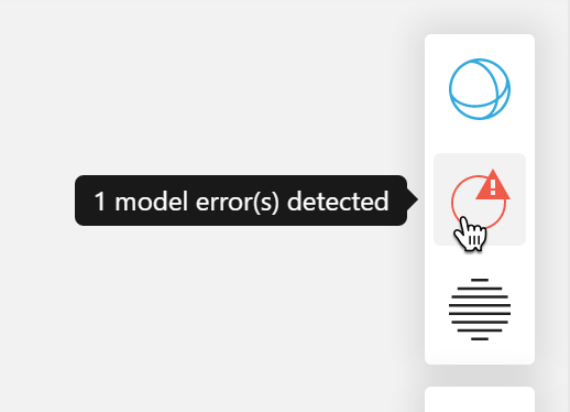
If any of the models on your current tray have mesh issues, you'll see this indication:

By clicking it you will go into Analysis Mode.

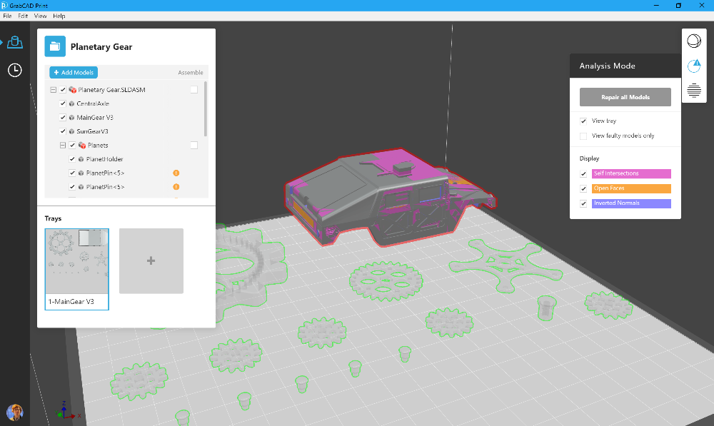
"Healthy" models are shown as transparent with a green outline, and models with problems are shown as solid with a red outline.
To repair your models, just hit "Repair all models"


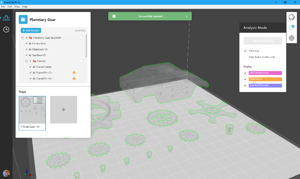
Once the repair is complete and all your models are in good shape, they will show as transparent with a green outline.

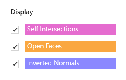
If you're interested getting a look at the specific problem areas, check out the model in the viewer. The issues will be represented by these colored sections. Hitting the checkboxes turns off the display of that type of issue.

If a model is indicating issues but you can't find the colored sections, it may be because the problems are on interior surfaces that cannot be seen in the viewer.
Once you're finished, click on the Model View button or hit the ESC key to return to Model View.
How Does it Work?
The analysis and healing both run MachineWorks technology* in the background, so you can count on a thorough analysis and a prompt repair.
When a large number of models are added at once, the analysis running in the background can cause some slowness. If this happens to you often, you can disable the automatic analysis from System Preferences > Model Insert Settings.
STLs and Mesh Problems
Inside the structure of a CAD file, abstract geometrical features like perfectly circular holes and smooth round fillets are described. Because these are written in the CAD system's own proprietaryformat, only the CAD system can read this data. This data is known as "BREP" data. STL files, by contrast, are made entirely of "tessellation" data, which is a collection of discrete faces (usually triangles) described by the coordinates of their corners. The order the corners are written determines which side of the triangle is "in" or "out" and this is referred to as the "surface normal." While a CAD file can describe a solid body bounded by shapes, STL files contain only the surface data, so you can see how gaps and errors in the data might cause problems for any software trying to build a solid body from it.
What Are the Types of Mesh Problems My STL Can Have, and How Do They Affect My Prints in General?
Because STL is a universal format, many different kinds of software can create them. Some of these programs may not record all the data properly resulting in errors for the next program to read them.
Self Intersections
This occurs when triangles contain mismatched coordinates, and they do not line up as expected. This creates an error because the surface can be in two places at once or create areas with zero thickness.
Open Faces
This occurs when there is missing data, resulting in a hole in the surface.
Inverted Normals
This occurs when the coordinates for a triangle are stored in an incorrect order, resulting in the "inside" face being inconsistent with the surrounding triangles.
Can These Problems Affect My CAD files Too?
GrabCAD Print does not generate toolpaths directly from the BREP data in your CAD file, and instead converts them to STL when you add this file to the project. The software we use to do this conversion is very good, but errors are still possible. Because of this, there may be errors shown in GrabCAD Print even with your native CAD files.
*Mesh analysis and healing provided by MachineWorks, Ltd., all trademarks and copyrights reserved.
