- PolyJet Legacy Printers
- Alaris30 V1
- Connex260
- Connex350/500
- Eden250
- Eden260
- Eden260V/VS
- Eden330
- Eden350
- Eden350V/500V
- J700 & J720 Dental
- J750/J735
- J750 Digital Anatomy
- Objet24/30 V2 Family
- Objet24/30 V3 Family
- Objet30 V5 Pro & Prime
- Objet260 Connex 1-2-3
- Objet260 Dental & Dental Selection
- Objet350/500 Connex 1-2-3
- Objet1000 Plus
- PolyJet Materials
- Agilus30 family
- Biocompatible
- Biocompatible Clear MED610
- Dental Materials
- Dental TrueDent Materials
- Dental TrueDent-D Materials
- Digital ABS Plus
- DraftGrey
- Elastico Clear/Black
- High Temperature
- PolyJet Support
- Rigur & Durus
- Tango
- ToughONE™
- MED610-DSG
- Transparent
- Vero ContactClear
- Vero Family
- Veroflex
- VeroUltra Opaque
- Vivid Colors
- Stereolithography Materials
- Somos® 9120™
- Somos® BioClear™
- Somos® DMX SL™ 100
- Somos® Element™
- Somos® EvoLVe™ 128
- Somos® GP Plus™ 14122
- Somos® Momentum™
- Somos® NeXt™
- Somos® PerFORM™
- Somos® PerFORM Reflect™
- Somos® ProtoGen™ 18420
- Somos® ProtoTherm™ 12120
- Somos® Taurus™
- Somos® WaterClear® Ultra 10122
- Somos® WaterShed® AF
- Somos® WaterShed® Black
- Somos® WaterShed® XC 11122
- Somos® WaterShed® XC+
Guide to Voxel Printing
Table of Contents:
Overview
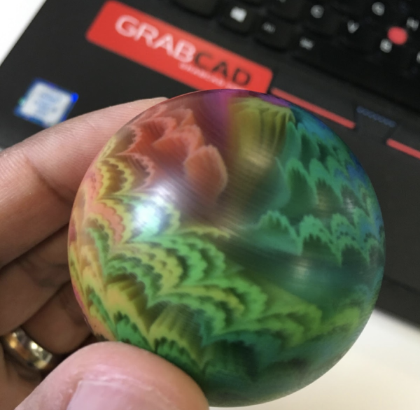
The GrabCAD Voxel Print Utility is a software add-on for GrabCAD Print which is available for purchase from your Stratasys sales representative and widens the capabilities of the kind of parts you can print on a Stratasys J750. Normally, colors and material settings can only be set uniformly for the whole body of a model or applied as a texture on the outer surface. Voxel Printing allows users to define a color for each individual point throughout the whole volume of the model. These points are called voxels — a three-dimensional version of the pixel. This type of printing enables the fabrication of parts with complex material distribution, such as a gradient or a sophisticated pattern.
The general workflow for Voxel Print jobs is as follows:
- In another program, such as Matlab, you slice the model and generate a set of .BMP or .PNG image files.
- In GrabCAD Print, you launch the Voxel Print Utility to create a GrabCAD Voxel File (*.GCVF) from your set of image files.
- You add the .GCVF file into your GrabCAD Print project and print.
Slice preparation guidelines
At this time, GrabCAD does not offer a tool to generate the slices from your 3D model. Users must use their own software, such as Matlab, to make the slices. The minimum number of slices is 30.
Layer Height
It is recommended that the layer thickness of the slices you prepare match the printed layer thickness. The printer layer thickness is:
- 0.014 mm = High Quality
- 0.027 mm = High Speed & High Mix
When printing the slices, if the slice thickness does not match the printer layer thickness, the printer compensates for the difference. This may include repeating or skipping of slices. For example, if you set the slice thickness to 0.0135 mm, and your printing mode is High Mix, the printer prints each image twice to reach the desired thickness of 0.027 mm.
XY Resolution
The J750 has different resolutions in X and Y.
- X resolution = 600 DPI
- Y resolution = 300 DPI
Therefore, if your part is a 1-inch cube, each slice will be 600x300 pixels in size.
Color Assignment
In normal color printing on the J750, parts may be any color. For instance, if your part is light-green, GrabCAD Print determines the right combination of Cyan, Yellow, and White in each slice to achieve the desired result. However, with voxel printing, you are creating the slices, so your slicing software needs to determine how to make the desired colors using only the available materials.
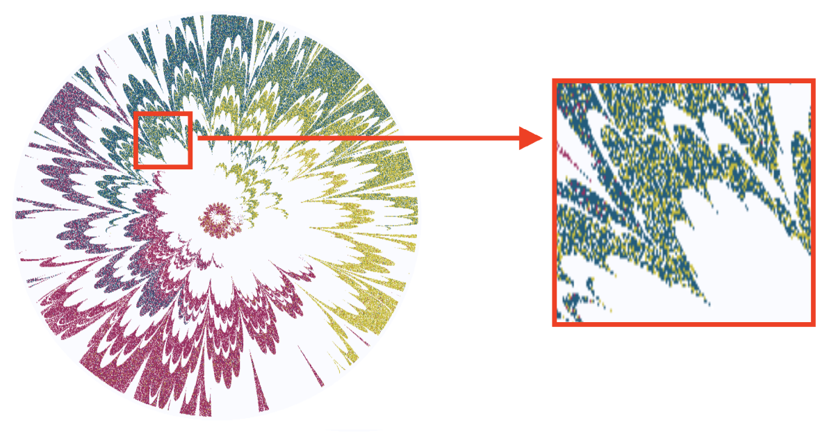
For reference, here are the color values for the PolyJet base materials:
| Base Resin | Red value | Green value | Blue value |
|---|---|---|---|
| FullCure720 | 255 | 255 | 170 |
| Tango+ | 255 | 255 | 100 |
| TangoBlack+ | 50 | 50 | 50 |
| Agilus30Clr | 255 | 255 | 100 |
| Agilus30Blk | 40 | 77 | 108 |
| Agilus30Wht | 255 | 255 | 255 |
| VeroFlexWT | 255 | 255 | 255 |
| VeroPureWht | 240 | 240 | 240 |
| VeroBlack or VeroFlexBK | 26 | 26 | 29 |
| VeroClear or VeroFlexCLR | 227 | 233 | 253 |
| VeroCyan or VeroFlexCY | 0 | 90 | 158 |
| VeroMgnt or VeroFlexMGT | 166 | 33 | 98 |
| VeroYellow or VeroFlexYL | 200 | 189 | 3 |
| VeroUltraClr or RGD821* | 247 | 247 | 247 |
| VeroMGT-V | 198 | 0 | 88 |
| VeroYL-V | 240 | 197 | 0 |
| VeroCY-V | 0 | 137 | 166 |
| VeroBlue | 156 | 208 | 237 |
| VeroGrey | 185 | 185 | 185 |
* RGD821 is VeroUltraClear for the J55.
Export Format
The Voxel Print Utility can create a GrabCAD Voxel File from BMP files or from PNG files.
The BMP method is available for historical reasons. For new developments only the PNG method is supported
- The PNG method uses one PNG image file for each layer.
- The Voxel Print Utility will match up the colors of the image to the materials loaded, therefore each image file must only use 6 distinct colors, or 3 for High Speed mode in addition to the background color.
- Please take precautions to prevent dithering near color boundaries, as this will cause "Too many colors" error in the Voxel Print Utility.
- Read more about the PNG method below.
- The BMP method uses one BMP image file per material for each layer.
- This means that there will be 6 files per layer, or 3 for High Speed mode. Each file is binary (1-bit).
- The number of slices for each material must be identical. If a certain material is not used in a specific slice, create an empty file for it.
- A configuration file determines how your files align to the materials loaded in the printer.
- Read more about the BMP method below.
Creating a GrabCAD Voxel File: PNG method
If your slicer generates PNG files, use this section. If your slicer outputs BMP files, skip ahead to the next section.
To generate GrabCAD Voxel Files from PNG files:
- Open GrabCAD Print and select a J750 printer.

- From the Apps menu, select Launch Voxel Print Utility.
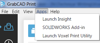
The Voxel Print Utility opens.
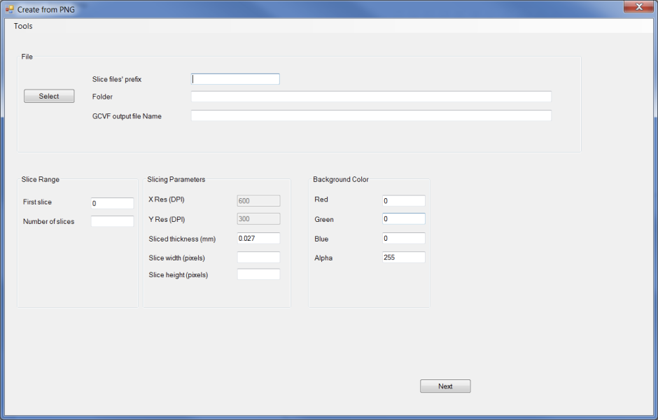
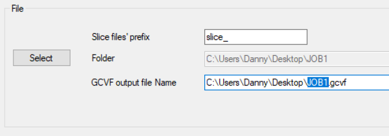
- In the Slice file prefix field, enter a prefix for the image files, such as slice_. This prefix is assigned to all image files.
- Click Select and navigate to the folder that contains the PNG files.
- After selecting the folder which contains the PNG files, the Folder and GCVF output file name boxes are filled in. You can modify the name of the GCVF file by editing this text.
-
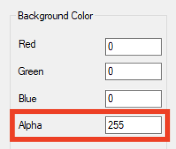
The information in the Slice Range, Slicing Parameters, and Background Color sections is automatically populated, but please verify the information. For instance, in this example, the background pixels are transparent, so A must be changed to 0.
-
Click Next. A progress bar shows the progress of the *.gcvf file generation. The file generation can take a few minutes, depending on the size of the file. If there are any errors with the file creation they will appear on this screen.
When the *.gcvf file generation is complete, the Material Mapping screen appears. The colors on the right side are the base colors that the Voxel Print Utility identified in the PNG files. To ensure color accuracy when printing the model on the PolyJet 3D printer, you need to match each of the colors on the right with a suitable PolyJet Model material (left side). For example, the blue color on the right side could be mapped to VeroBlue or VeroCyan.
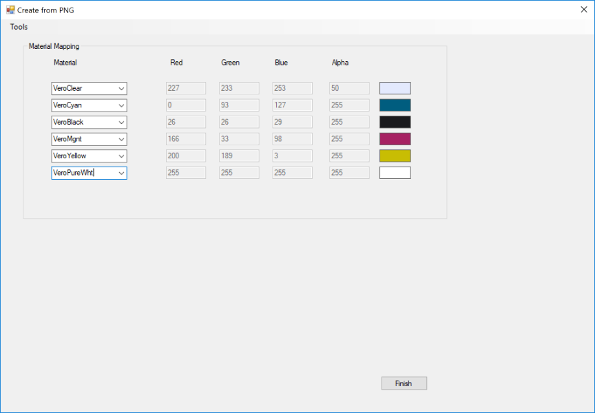
- In the Material column, select each PolyJet Model material you want to use based on the color shown on the right side of the screen.
Note: Before printing, make sure that the Model materials that you assigned are loaded in the material cabinet. - Click Finish. The following message appears:
- Click OK to close this message
- Close the Voxel Printing Utility
- To print this file, continue reading here.
Creating a GrabCAD Voxel File: BMP method
If your slicer generates BMP files, use this section. If your slicer outputs PNG files, use the previous section instead.
In the BMP method, each printed layer is defined by 6 files, one for each material loaded, or 3 files per layer in High Speed mode. The BMP method also requires the additional step of creating the configuration file.
Here are some important things to note about the BMP method:
- The image files need to be 1-bit (binary) BMP format.
- BMP LUT 0 (black) for voxels in which the material is not printed.
- BMP LUT 1 (white) for voxels in which the material is printed.
- The BMP files should be named by their materials. The exact material name does not matter, since the exact material names are specified in the configuration file.
- BMP files are not required to define the Support material. GrabCAD Print calculates where Support material is needed.
BMP Method: Creating the configuration file
When printing BMP slices, you need to create a voxel configuration text file. You do this in a text editor, such as Notepad. Below is a sample of a voxel configuration text file.
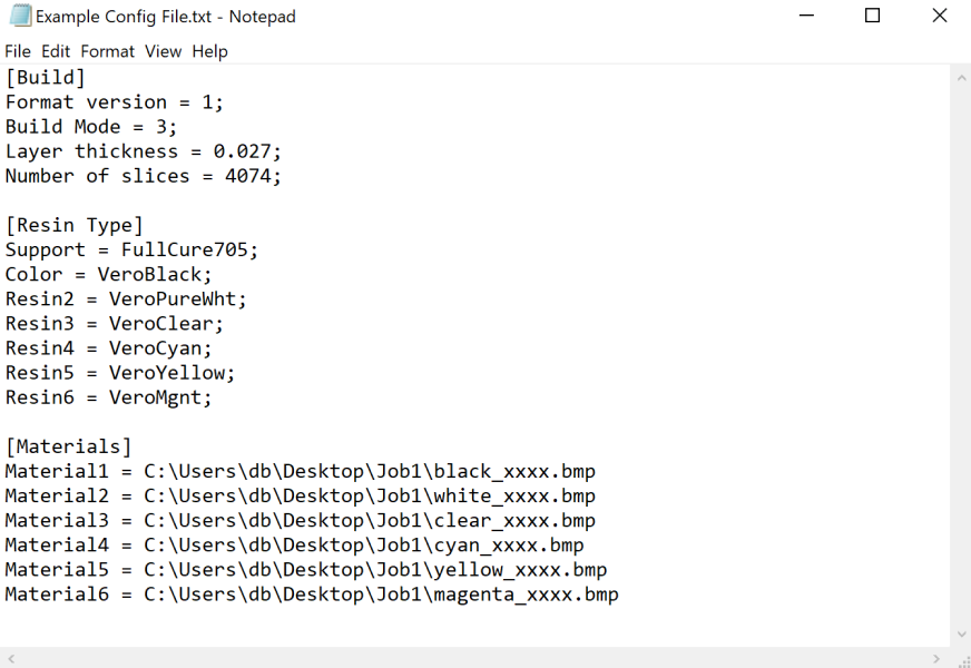
Note: It is crucial that the configuration file is formatted properly. Please follow these instructions carefully to create the configuration file.
In the sample above, you can see the three sections of the file. They are the Build section, the Resin Type section, and the Materials section. Use the information below to fill in the sections, and then save the file with a *.txt file extension. The name you choose for configuration text file will be the job name in the Manager queue.
Build Section:
| Example text | Explanation |
|---|---|
| [Build] | This is a section header for the following parameters. Do not add a semicolon (;) at the end of the header. |
| Format Version = 1; | Keep this value as ‘1’. |
| Build Mode = 3; | Enter a printing mode.
|
| Layer thickness = 0.027; | Set the layer thickness that you used to slice the model. ( See above) |
| Number of slices = 4074; | Set the total number of slices for each material (see Note below). Important: GrabCAD Print crashes if this number is not correct. |
Note: The number of slices may be different than the number in the file of the last slice. For instance, if the first slice is slice_0.png and the last slice is slice_4073.png, then the number of slices is 4074.
Resin Type Section:
| Example text | Explanation |
|---|---|
| [Resin Type] | This is a section header for the list of material names in the printer. Do not add a semicolon (;) at the end of the header. |
| Support = FullCure705; | Set the Support material name. |
| Color = <Model material1 name>; | Set the name of a material loaded. |
| Resin2 = <Model material2 name>; | Set the name of a material loaded. |
| Resin3 = <Model material3 name>; | Set the name of a material loaded. |
Resin4 = <Model material4 name>; |
Set the name of a material loaded. |
| Resin5 = <Model material5 name>; | Set the name of a material loaded. |
| Resin6 = <Model material6 name>; | Set the name of a material loaded. |
For High Speed mode, omit the last three rows, since only three materials are loaded.
Make sure that you list the Model materials in the order they are loaded in the material cabinet compartments.
Even if the job only requires some of the materials loaded, be sure to list all the materials for your print mode: 6 for High Quality and High Mix, 3 for High Speed.
The material names need to be listed exactly as they appear in the Stratasys software (not as they appear on the cartridge). For example, if the material name in the software is TangoBlack+, and on the cartridge it is TangoBlackPlus, enter TangoBlack+ in the text file. Below is a list of the material names as they appear in the software:
— FullCure720
— Tango+
— TangoBlack+
— VeroClear
— VeroCyan
— VeroMgnt
— VeroYellow
— VeroBlack
— VeroPureWht
— VeroBlue
Materials Section:
| Example text | Explanation |
|---|---|
| [Materials] | This is a section header for the paths of the slice files. Do not add a semicolon (;) at the end of the header. |
| Material1 = C:\Users\db\Desktop\Job1\black_xxxx.bmp | Path to the slices for "Color" material in the Resin Type section. |
| Material2 = C:\Users\db\Desktop\Job1\white_xxxx.bmp | Path to the slices for "Resin2" material in the Resin Type section. |
| Material3 = C:\Users\db\Desktop\Job1\clear_xxxx.bmp | Path to the slices for "Resin3" material in the Resin Type section. |
| Material4 = C:\Users\db\Desktop\Job1\cyan_xxxx.bmp | Path to the slices for "Resin4" material in the Resin Type section. |
| Material5 = C:\Users\db\Desktop\Job1\yellow_xxxx.bmp | Path to the slices for "Resin5" material in the Resin Type section. |
| Material6 = C:\Users\db\Desktop\Job1\magenta_xxxx.bmp | Path to the slices for "Resin6" material in the Resin Type section. |
For High Speed mode, omit the last three rows, since only three materials are loaded.
The x's represent the maximum number of digits in the slice number. For example, if your last slice is slice_4073.bmp use four x's.
The x's must be lowercase.
BMP Method: Creating the GrabCAD Voxel File
To generate GrabCAD voxel files from BMP files:
- Open GrabCAD Print and select a J750 printer.

- From the Apps menu, select Launch Voxel Print Utility. The Voxel Print Utility opens.
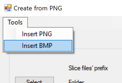
- From the Tools menu, select Insert BMP.
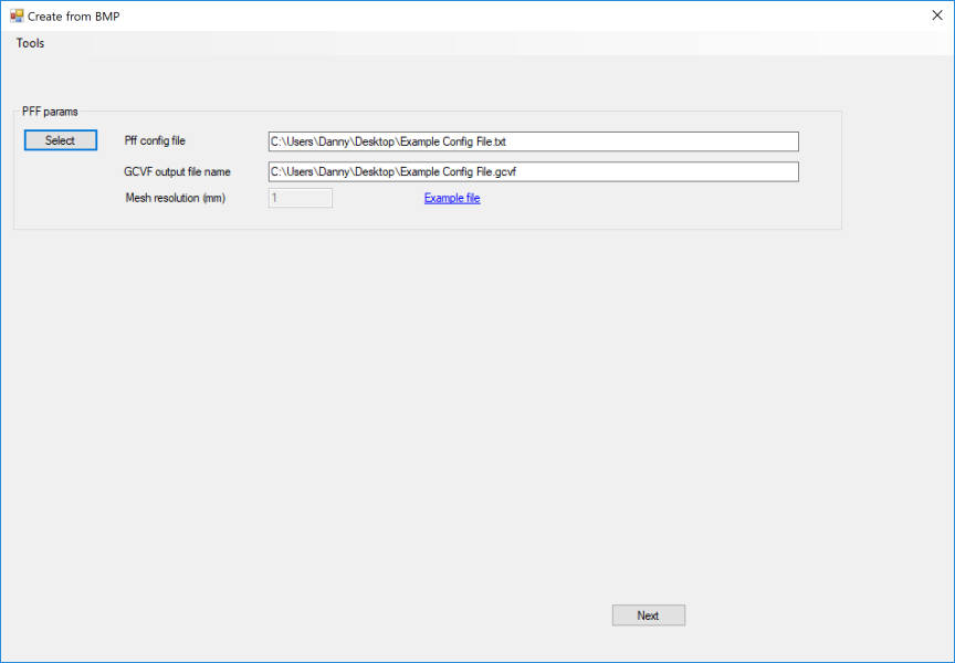
- In the Pff params area:
- Click Select and navigate to the folder that contains the BMP files.
- Select the voxel configuration text file (*.txt file) you created. The *.txt file is also known as the Print From File (Pff) config file.
- In the GCVF output file name field, enter the desired location and name of the generated *.gcvf file. The path must contain a *.gcvf file extension, as shown in the figure below.
- Click Next. A progress bar shows the progress of the *.gcvf file generation. The file generation can take a few minutes, depending on the size of the file.
When done, the following message appears. - Click OK to close the message.
- Close the Voxel Printing Utility.
- To print this file, continue reading below.
Printing a Voxel Print job
To print a voxel print job:
- In GrabCAD Print, ensure that the following preferences are set:
- From the File menu, select Preferences > PolyJet
- Check "Enable Voxel Print" and click Save.
- From the File menu, select Add Models.
- Navigate to the location of the GCVF file you generated, select it, and click Open.
- GrabCAD Print validates the file and loads it. While you are in model view, please note the following:
- During the GCVF file generation, an STL file of the model is created. GrabCAD Print uses this STL file to display the model on the tray, as shown in the above figure. Since it is not possible to view the colors you assigned to the model in GrabCAD Print, it is very important that you make sure that the correct materials are loaded in the material cabinet.
- An exclamation mark icon appears near the filename if the GCVF file contains a material that is not loaded in the tray materials. If you do not load the required material in the printer, the printer ignores the material assignment in the GCVF file, and prints the file as an STL file using a default material.
- Glossy surface finish is not available, only matte.
- Grid style selection is available.
- You can add copies of the model on the tray by right-clicking on the model and selecting Duplicate.
- The Scale and Orient options are not available. To change the size or the orientation of the model, you need to generate a new *.gcvf file with the desired size and/or orientation.
- You can use the Arrange (tray) option. Tray arrangement is performed according to the orientation defined in the BMP/PNG files.
- Do not select the Optimize check box. Currently, it does not work properly with *.gcvf files.
- Click Print to send the file to print.

