Printers
- PolyJet Legacy Printers
- Alaris30 V1
- Connex260
- Connex350/500
- Eden250
- Eden260
- Eden260V/VS
- Eden330
- Eden350
- Eden350V/500V
- J700 & J720 Dental
- J750/J735
- J750 Digital Anatomy
- Objet24/30 V2 Family
- Objet24/30 V3 Family
- Objet30 V5 Pro & Prime
- Objet260 Connex 1-2-3
- Objet260 Dental & Dental Selection
- Objet350/500 Connex 1-2-3
- Objet1000 Plus
Materials
- PolyJet Materials
- Agilus30 family
- Biocompatible
- Biocompatible Clear MED610
- Dental Materials
- Dental TrueDent Materials
- Dental TrueDent-D Materials
- Digital ABS Plus
- DraftGrey
- Elastico Clear/Black
- High Temperature
- PolyJet Support
- Rigur & Durus
- Tango
- ToughONE™
- MED610-DSG
- Transparent
- Vero ContactClear
- Vero Family
- Veroflex
- VeroUltra Opaque
- Vivid Colors
- Stereolithography Materials
- Somos® 9120™
- Somos® BioClear™
- Somos® DMX SL™ 100
- Somos® Element™
- Somos® EvoLVe™ 128
- Somos® GP Plus™ 14122
- Somos® Momentum™
- Somos® NeXt™
- Somos® PerFORM™
- Somos® PerFORM Reflect™
- Somos® ProtoGen™ 18420
- Somos® ProtoTherm™ 12120
- Somos® Taurus™
- Somos® WaterClear® Ultra 10122
- Somos® WaterShed® AF
- Somos® WaterShed® Black
- Somos® WaterShed® XC 11122
- Somos® WaterShed® XC+
Create Warp-Adjusted Models with the Accuracy Center
The Accuracy Center is a feature of GrabCAD Print Pro. Click here to learn more.
How it works
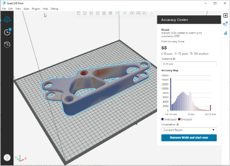
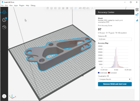
Accuracy Center takes a scan of your printed part, aligns it to your design model, compares the two, and scores the accuracy of the print against the design. If required, the Accuracy Center can account for warp and curl by replacing the model with a Warp-Adjusted Model (WAM™) to help you achieve a more accurate part with fewer design iterations.
| Before | After |
|---|---|

|

|
Selecting and using a scanner
When selecting a Scanner for use with Accuracy Center:
- A scanner with +/- 25 microns or better is recommended for parts 6 inches or less, and +/- 50 microns or better for parts between 6 and12 inches.
- Leave your scan data as complete as possible. The Accuracy Center won't correct areas corresponding to large gaps in scan data.
- Small holes are OK. Do not fill or patch the holes in the scan data. Set scanner software to leave the holes open.
- Export scan data as an STL file with file size less than 300 mb. The typically useful range is 30,000 to 1 million vertices or triangles.
- Blue laser scanners perform much better than red laser scanners on FDM materials. Structured light / phase image scanners can also work well with appropriate settings for your material.
- Materials that are shiny or dark may require or be much easier with scanning spray such as AESUB Blue vanishing spray.
How to use the Accuracy Center
- Begin by printing the model in the settings of your choosing, then Save the project for later. It's best to use single-body CAD files, not multi-body files or STLs.
- Once the model is printed and support has been removed, scan it. Keep track of support removal parameters, for example how long your part was in the support removal bath so you can duplicate the process later.
- Open the GC Print project, select the model, then click on Accuracy Center.
- Hit Import Scan to bring in the scan data. Since the scan is a purely mesh format such as STL or PLY, you must select a unit of measurement. This is likely a setting on your scanner's software.
-
You will usually use the default settings for "Keep Base Flat" and "Horizontal Surfaces".
You can switch off "Keep Base Flat" if you have a part without a flat base or if you want to allow changes to the base of the part.
For Horizontal Surfaces, the default option "Preserve" allows horizontal surfaces to be translated uniformly, and prevents splitting them into different layers during the WAM process. Use the "Pin" option to prevent any correction of horizontal surfaces. Use the "Free Adjust" option to enable full correction of horizontal surfaces including adding layer contours (splitting layers) to correct non-flatness. - Hit Compare and Create WAM, and the Accuracy Center will automatically align the scan data with the real model and provide an Accuracy Score. If the score is zero, this means alignment has failed. You may have selected the wrong units, or the CAD file may be a multi-body file.
- Accuracy Center results are shown on the model and in a histogram, with blue indicating undersize regions and red indicating oversize ones. The range of the colors and width of the histogram can be adjusted with the tolerance.
- The Warp Adjusted Model is automatically created in the processing step. When you exit the Accuracy Center, the model on the tray has been replaced by the WAM and is ready to be printed. If you are satisfied with your Accuracy Score and comparison, click Restart to return to the import step, and Return to Model View to exit the Accuracy Center.
-
You can import a scan of the printed WAM to see the improvement that was created. The heatmap colors will be less pronounced and the score will be higher. A new WAM iteration is created whenever you upload a new scan.
You can continue to iterate as many times as you wish and continue to improve the accuracy (to the limit of random error). Most projects get the majority of the benefit with a single WAM iteration. You may want 2 or 3 iterations for high volume production parts.
