2 Printer Setup
This chapter describes basic setup of the F123 Series.
The printer’s Welcome Kit contains the Welcome Insert document and common tools you will need to maintain the printer. Use the following figures and tables to identify the contents of the Welcome Kit.
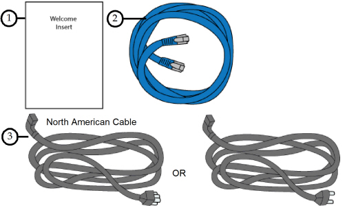
Figure 1: Welcome Kit Contents - Documents and Cables
|
# |
Item |
Description |
|---|---|---|
|
1 |
Welcome Insert Document |
Contains instructions for downloading the F123 Series User Guide (this document). |
|
2 |
RJ45 Cable |
This cable is used to establish a network connection between the F123 Series printer and your Ethernet network. See “Making the Network Connection” (page 7). |
|
3 |
AC Cable (North American or European) |
This cable provides the power connection to the printer. See “Connecting the Power Cable” (page 8). Select the appropriate cable for your location (North American cable or European cable). |
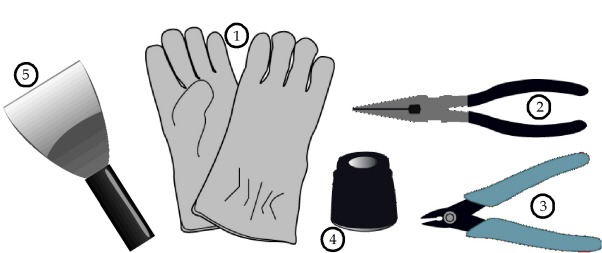
Figure 2: Welcome Kit Contents - Tools
|
# |
Item |
Description |
|---|---|---|
|
1 |
Leather Safety Gloves |
Printer components may be extremely hot. To prevent burns or other injuries, these gloves should be worn any time you see the gloves safety sign throughout this document. See “Product Safety Signs” (page 2). |
|
2 |
Needle Nose Pliers (71/8”) |
Occasionally, you may need to use pliers to aid in the clearing of debris which have accumulated on the head and/or tips (see “Clean/Inspect Tip Wipe Assemblies” (page 12)). |
|
3 |
5” Cutter |
These are used to cut a material spool’s filament when unloading and removing materials from the printer. See “Unloading Material” (page 7). |
|
4 |
Loupe Magnifier |
This tool is included to aid you with performing a Manual Tip Calibration which requires you to view small toolpath relationships. See “Manual Tip Calibration” (page 5). |
|
5 |
Scraper |
This tool is used to scrape parts or material off the substrate. |
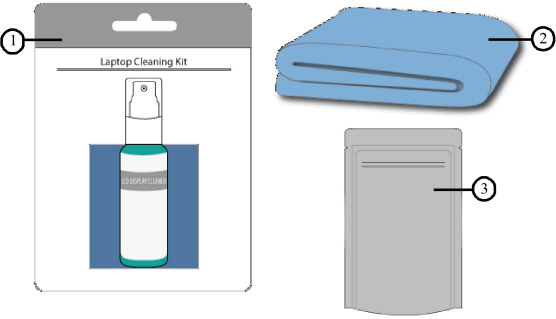
Figure 3: Welcome Kit Contents - Cleaning Supplies & Storage Materials
|
# |
Item |
Description |
|---|---|---|
|
1 |
Touchscreen Cleaning Kit |
From repeated use, the touchscreen may become dirty and occasionally need to be cleaned. Only use suitable LCD cleaning agents when cleaning the touchscreen. See “Cleaning the Touchscreen Display” (page 15) for cleaning instructions. |
|
2 |
Microfiber Cloth |
Various components of the printer may become dirty and occasionally need to be cleaned. Only use a suitable microfiber cloth to clean these components. See “Cleaning the Exterior Surface of the Printer” (page 15) for cleaning instructions using this cloth. |
|
3 |
Resealable Bag (x3) |
When unloaded, non-empty model and support material spools should be stored within these bags to prevent moisture from contacting the spool’s filament (see “Handling/Storing Materials” (page 11)). |
The following items are not located within the Welcome Kit. Instead, they reside within the oven chamber and the storage drawer. The items found within the oven chamber must be removed before turning the printer power on.
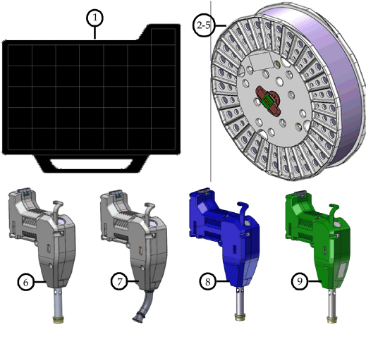
Figure 4: Additional Components - Startup Materials
|
# |
Item |
Description |
|---|---|---|
|
1 |
Substrate (x16) |
A substrate is the surface upon which a part is built. The same substrate is used for all model materials, including PLA. See “Preparing the Printer” (page 15) for more information. |
|
2 |
ABS Model Material Spool |
Material spool containing 60 in3 (984 cc) of ABS model material (see “Materials Used” (page 16)). |
|
3 |
QSR Support Material Spool |
Material spool containing 60 in3 (984 cc) of QSR support material (see “Materials Used” (page 16)). |
|
4 |
PLA Material Spoola |
Material spool containing 60 in3 (984 cc) of PLA material (see “Materials Used” (page 16)). |
|
5 |
TPU 92A Material Spoolb |
Material spool containing 60 in3 (984 cc) of TPU 92A material (see “Materials Used” (page 16)). |
|
6 |
PLA Model Heada |
Print head for use with PLA model material only (see “Print Heads” (page 14)). |
|
7 |
PLA Cooling Modulea |
Cooling module to be used in conjunction with the PLA model head (see “Print Heads” (page 14)). |
|
8 |
TPU 92A Model Headb |
Print head for use with TPU 92A model material only (see “Print Heads” (page 14)). |
|
9 |
ABS-CF10 Model Head |
Print head for use with ABS-CF10 model material only (see “Print Heads” (page 14)). CF10 head is an option and not included with every system. |
Follow the Site Preparation Guide to ensure that your facility is effectively and safely prepared for printer installation. Do not proceed with the following sections until the “Unpacking the Printer” section of the Site Preparation Guide has been completed. When installation is complete, perform the following setup tasks.
•Verify that the startup materials have been removed from the oven chamber. If not, remove these items. See Figure 4 (page 4) for details on the startup materials.
•Open the top cover and ensure that the orange clip has been removed from the X belt, and the orange tie wrap has been removed from the X motor. If not, remove the orange clip and/or orange tie wrap securing these components.
|
|
Caution: Unstable Object. The stability pads are used to stabilize the printer after it has been moved to its desired operating location. The stability pads must be set prior to printer operation. |

To stabilize the printer:
1.Roll the printer to its desired operating location and verify that minimum space requirements have been met.
|
Side |
Clearance |
|---|---|
|
Side Clearance |
Minimum 4 inches (10.16 cm) on each side |
|
Rear Clearance |
Minimum 6 inches (15.24 cm) |
|
Front Clearance |
Minimum 20 inches (50.80 cm) |
|
Overhead Clearance |
Minimum 20 inches (50.80 cm) |
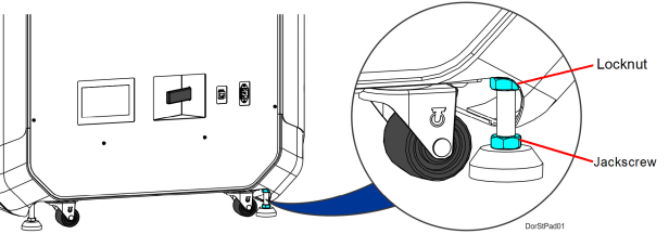
2.Thread the stability pad jackscrew downward until the stability pad makes contact with the floor (see Figure 5).
3.Turn the jackscrew an additional 1-2 turns downward and set the locknut firmly against the lower frame member (see Figure 5).
|
|
Ideally, each caster wheel will remain in slight contact with the floor and using minimal force, be able to be rotated. |

4.Repeat step 2 and step 3 above to set all remaining stability pads.
Figure 5: Stability Pad Jackscrew Adjustment
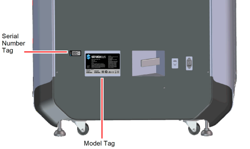
Use the following tags to identify your printer:
•Serial Number Tag - Refer to this number when requesting service. You can also locate the printer’s serial number via the Maintenance page of the User Interface (see “System Odometers” (page 58) for more information).
•Model Tag - The printer’s model number, part number and power requirements are given on this tag. This tag also lists all patent numbers associated with the printer, some FCC compliance information, voltage warnings, and the Stratasys web address.
Both tags are located on the back side of the printer near the bottom, and are typically placed near the printer’s power connection. Use the information on these tags when identifying your printer with Customer Support.
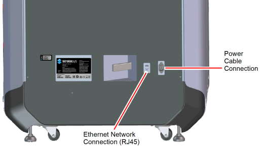
Processed job files can be transferred from GrabCAD Print to the F123 Series printer through your facility’s Ethernet network. An RJ45 network connector is located on the right, rear corner of the printer (as viewed from the rear). See Figure 7 for the network connection location.
|
|
A 15 foot (4‘.6m) network patch cable is supplied with the printer and located in the welcome kit. Facilities having network connection points further from the printer than can be reached by the supplied cable are responsible for the procurement of an appropriate cable. |
|
|
Caution For users in Japan; A power cable is provided for connecting the printer to the AC electric source. Do not use it with other equipment. |
To connect the power cable:
1.Connect the male end of the supplied power cord (US or European) directly into a grounded electrical outlet.
2.Connect the female end of the power cord directly into the socket located on the back of the printer (see Figure 7).
|
|
Warning: Electrical Shock Hazard. The power cord serves as the disconnect device. The socket outlet must be easily accessible. |

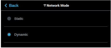
This section is provided in case you need to change your network settings. Within the Network page you can set your printer’s address type to Static, Dynamic (DHCP), or Wi-Fi; Dynamic is selected by default.
•Static address - you must enter an IP address, subnet mask, and gateway address for the printer (provided by the system administrator). Once entered, the address will not change.
•Dynamic address (DHCP) - a network server or PC will generate an IP address for the printer. A different IP address may be generated from time to time by the server or PC.
•Wi-Fi address - the printer will scan for and allow you to connect to an available Wi-Fi network (if the Wi-Fi dongle has been installed).
To configure your printer’s network address settings:
1.Power ON the printer, see “Powering ON the Printer” (page 1).
2.Open the Tools page by pressing the Tools button within the Navigation Menu (see Table 1 (page 2)).
3.Open the Network page by pressing the Network button within the Tools page (see Figure 36 (page 39)).
4.The Connection Type row allows you to select between a wired or wireless network. The option selected will determine the configurable settings displayed within the Network page.
•Selecting the Wired option will allow you to select between a Dynamic or Static network mode.
•Selecting the Wireless option will configure the pinter to use a Wi-Fi network. You will need to scan for a wireless network and enter the security settings for the selected network (if required) to complete the configuration. Please note that the availability of the Wireless option depends upon the configuration purchased with your printer.
5.After selecting the radio button corresponding to the connection type you’d like to use (wired or wireless) press the Back button in the upper-left corner of the page to return to the Network page.
6.For wired networks:
a.The Network Mode row will be displayed. Press anywhere within this row.
b.Select either the Static or Dynamic radio button to enable that network address type. Depending on the option selected, you may need to configure additional information within the Network page.
Figure 8: Wired Network Selection
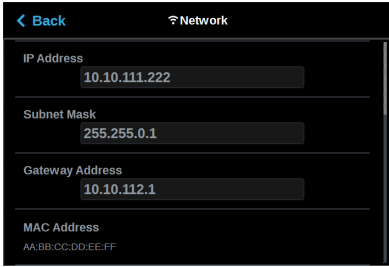
•If the Static option is enabled, you must manually configure the IP Address, Subnet Mask, and Gateway Address fields.To configure this information simply touch a field on the screen to select it and then use the keypad displayed to enter address information.
i.Touch anywhere on the screen outside of the keypad to exit and close the keypad.
Figure 9: Static Network Configuration

ii.Scroll to the bottom of the page and press the Apply button when finished to save the network configuration.
iii.Press the Back button in the upper-left corner of the page to return to the Network page.
Figure 10: Apply Changes Button

•If the Dynamic option is enabled, no additional configuration is necessary as a network server or PC will automatically generate an IP address for the printer. A different IP address may be generated from time to time by the server or PC; the generated IP address will be displayed within the IP Address field of the Network page, and corresponding Subnet Mask and Gateway Address information will also be displayed.
•Press the Back button to exit the page and return to the Tools page.
Figure 11: Dynamic Network Configuration
7.For wireless networks:
a.The Available Networks row will be displayed (Wi-Fi dongle must be installed). Press anywhere within this row.
b.Press the Scan button; the printer will scan for an available wireless (Wi-Fi) network.
Figure 12: Scan for Wireless Network
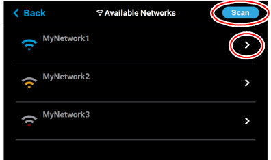
c.A list of available networks will be displayed; select the wireless network you’d like to connect to by pressing anywhere within the row.
d.A page will be displayed containing the details of the selected Wi-Fi network. Within this page use the keyboard to enter the password and/or username required to connect to the network.
Figure 13: Enter Wi-Fi Network Information
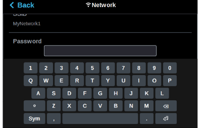
e.When finished, touch anywhere on the screen outside of the keypad to exit and close the keypad.
f.Scroll to the bottom of the page and press the Connect button to save the network configuration.

g.Press the Back button to exit the page and return to the Network page. The name of the selected wireless network will be displayed within the Available Networks row.
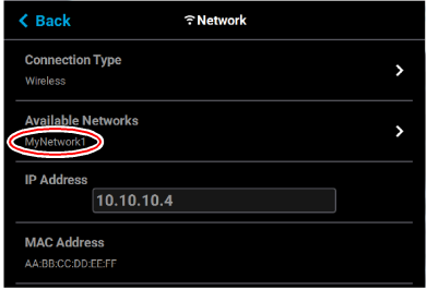
h.Press the Back button to exit the page and return to the Tools page. The Network button will refresh and a blue indicator will be displayed indicating that the printer is configured for a Wi-Fi network.
Figure 15: Enter Network Settings Dialog

Install the GrabCAD Print software on a facility workstation. Navigate to http://help.grabcad.com/article/197-sign-up-download-and-install and follow the on-screen instructions.
Connecting to the F123 Series Printer
Add the F123 Series printer to the GrabCAD Print application. Navigate to http://help.grabcad.com/article/198-connect-your-printers and follow the on-screen instructions.
Setting the Printer’s Date and Time
In order to ensure accurate build times, the printer’s clock must be set correctly. If you find that your printer’s date and/or time are incorrect you can update them using GrabCAD Print. To do so, navigate to http://help.grabcad.com/article/196-printer-firmware-management and follow the procedure for “Changing your printer’s clock time”.
Updating the Controller Software Version
Update the controller software if necessary. See “Updating Controller Software” (page 1).
If necessary, adjust the tip wipe height. See “Tip Wipe Height Adjustment” (page 16).