This chapter describes various maintenance tasks that will routinely need to be performed on the F123 Series.
Controller Software can be updated using one of the following three methods:
•Installing from a USB Flash drive that contains the software update file
•Navigating to the update file on your workstation PC with the Insight software application; After placing the printer into upgrade mode (see “Update Software” (page 58)), navigate to and install the upgrade file from its saved location on your workstation PC.
•Selecting push notifications automatically sent via GrabCAD Print;
After receiving a notification from GrabCAD Print that a software upgrade is available, follow the on-screen prompts and instructions to install the upgrade.
You have the option of updating Controller Software via any of these methods; however, the USB Flash drive method is the preferred method.
|
|
Updating Controller Software will erase all job files from the Job Queue (files within the Sample Queue (Internal Storage) will be retained). After completing the software upgrade, you will need to resend jobs to the printer. |

1.Save the software upgrade file to a USB flash drive.
2.Insert the USB flash drive into one of the available USB ports on the F123 Series printer.
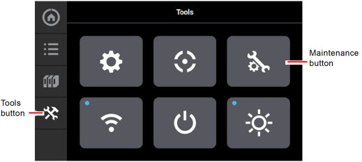
3.On the printer touchscreen, open the Tools page by pressing the Tools button within the Navigation Menu.
Figure 1: Tools Page
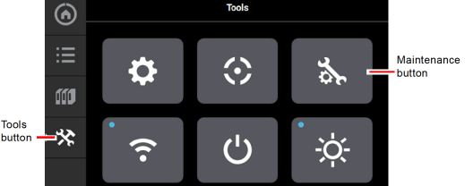
4.Open the Maintenance page by pressing the Maintenance button within the Tools page.
Figure 2: Maintenance Page
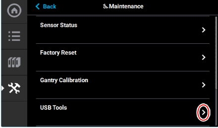
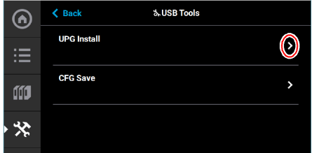
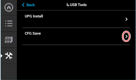
5.From the Maintenance Page, select USB Tools and then select UPG Install.
Figure 3: USB Tools
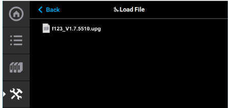
6.Select USB.
Figure 4: Load File
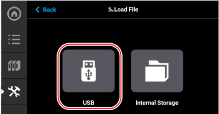
7.Navigate to and select the upgrade file from its saved location on the USB drive.
Figure 5: Upgrade File Location
8.The upgrade file will install. The screen will display the status until the upgrade is complete.
Figure 6: Upgrade Status

|
|
Updating Controller Software will erase all job files from the Job Queue (files within the Internal Storage will be retained). After completing the software upgrade, you will need to resend jobs to the printer. |
To update Controller Software via GrabCAD Print, navigate to http://help.grabcad.com/article/196-printer-firmware-management and follow the procedure for “Updating the printer’s firmware”.
Insight Software Method (F370 only)
If the printer has a weak network connection or does not allow for automatic updates, you can manually download Controller Software updates by performing the following steps:
1.Open the Maintenance page by pressing the Maintenance button within the Tools page (see Figure 36 (page 39)).
2.Locate the Update Software row within the page. Press anywhere within the row to open the Update Software page (see Figure 75 (page 58)).
3.The Update Software page will open and the printer will automatically be put into software upgrade mode, allowing it to receive the software upgrade. The following is displayed on the touchscreen while the printer is in software upgrade mode.
Figure 7: Printer In Software Upgrade Mode

|
|
All recent calibration data (i.e. tip offset values) as well as printer settings and configurations are automatically retained during the software upgrade process. Files sent to the Job Queue via Ethernet or Wi-Fi connection or transferred to the printer from a USB flash drive are not retained. |
4.From your workstation PC’s Start Menu, navigate to All Programs > Insight (installed version) > Control Center (installed version) or double-click the Control Center shortcut (if available).
5.Within Control Center, select the Services tab. Ensure that your F370 Series printer is selected from the drop-down menu then click the Update Software button.
Figure 8: Control Center Update Software

6.Control Center will begin establishing a connection with the printer. Once a connection is established, the workstation PC’s file explorer will open.
7.Browse to the location of the .upg software upgrade file.
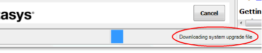
8.Select the *.upg file to be downloaded and then click Open. Control Center will begin sending software to the printer. Progress is indicated within the bottom of the Control Center window as well as on the touchscreen.
Figure 9: Software Download Progress

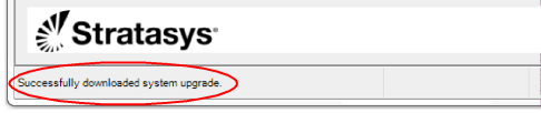
9.Once the software upgrade is successfully downloaded to the printer an indicator will be displayed within the bottom of the Control Center window.
Figure 10: Software Upgrade Successfully Downloaded
10.The touchscreen will refresh to indicate that the printer is verifying the upgrade file.
|
|
The verification process will take several minutes; please be patient. |
Figure 11: Verifying Software Upgrade

11.Once the verification process is complete, the printer will automatically reboot and begin installing the upgrade file. A variety of output will be displayed on the touchscreen during the installation process.
|
|
The installation process will take several minutes; please be patient. |
12.Once the Controller Software upgrade is installed the printer will conduct its regular startup process and automatically perform an XY Gantry Calibration (see “Powering ON the Printer” (page 1) for details).
Exporting System Configuration (.CFG) File
If your system is receiving fault determination codes, you may need to export a configuration (.cfg) file from your system to send to Customer Support. System configuration files can be exported using one of the following three methods:
•Saving to a USB Flash drive directly from the F123 Series printer
•Saving to a location on your workstation PC using the Insight software application
•Saving via GrabCAD Print
You have the option of exporting system configuration files via any of these methods; however, the USB Flash drive method is the preferred method.
1.Insert the USB flash drive into one of the available USB ports on the F123 Series printer.
2.On the printer touchscreen, open the Tools page by pressing the Tools button within the Navigation Menu.
Figure 12: Tools Page
3.Open the Maintenance page by pressing the Maintenance button within the Tools page.
Figure 13: Maintenance Page
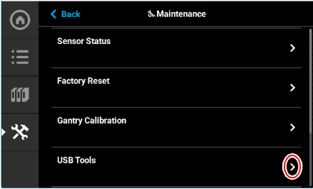
4.From the Maintenance Page, select USB Tools and then select CFG Save.
Figure 14: USB Tools
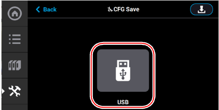
5.Select USB.
Figure 15: CFG Save
6.Navigate to a save file location on the USB drive and select the Download button.
Figure 16: Save File Location
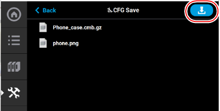
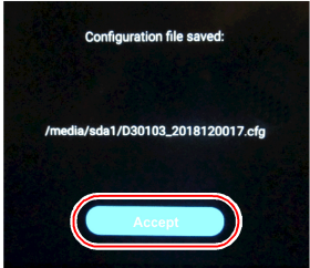
7.The configuration file will download to the USB flash drive. Select Accept when the file download is complete.
Figure 17: Configuration File Saved
For detailed instructions on exporting a system configuration file navigate to:
http://help.grabcad.com/article/196-printer-firmware-management and follow the procedure for ‘Exporting the printer configuration’.
Insight Software Method (F370 Only)
1.From your workstation PC’s Start Menu, navigate to All Programs > Insight (installed version) > Control Center (installed version) or double-click the Control Center shortcut (if available).
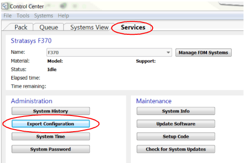
2.Within Control Center, select the Services tab. Ensure that your F370 Series printer is selected from the drop-down menu then click the Export Configuration button.
Figure 18: Control Center Export Configuration
3.Browse to the directory where you wish to save the configuration file.
4.Click on the Save button.
5.Close Control Center.
|
|
Warning: Hot Surface Hazard Always wear proper heat protective gloves and clothing when handling items inside the oven, as surfaces within the oven can be very hot. |

Maintenance tasks must be performed on a regular basis in order to maintain optimal system operation. Table 1 outlines the general maintenance schedule for the F123 Series. Detailed instructions for each task make up the rest of this chapter.
Table 2 lists part numbers for various replacement consumable items. Use the part numbers listed in this table when ordering replacement parts from Stratasys or your regional Stratasys office.
|
Part Number |
Description |
|---|---|
|
123-00401-S |
Model Head (standard) |
|
123-00401-S |
Support Head (standard) |
|
123-00307-S |
PLA Model Head |
|
123-00301-S |
PLA Cooling Module |
|
123-00321-S |
TPU 92A Model Head |
|
123-00601-S |
ABS-CF10 Extrusion Head |
|
123-00302-S |
F170 substrate 1 box of 16 |
|
123-00303 |
F270 substrate 1 box of 16 |
|
123-00304 |
F370 substrate 1 box of 16 |
|
123-00305 |
Tip shield kit - 4 sets |
|
123-00306 |
2-pack of tip wipe assemblies (see “Clean/Inspect Tip Wipe Assemblies” (page 12)). |
|
123-00314-S |
F370 high temp substrates (Diran only) 1 box of 16 |
|
|
Warning: Hot Surface Hazard Always wear proper heat protective gloves and clothing when handling items inside the oven, as surfaces within the oven can be very hot. |
The purge chute is designed to guide purged material debris from the tip wipe assemblies to the bottom of the oven chamber for disposal. Purged material debris then collects within the bottom of the oven chamber, beneath the platen. Do not allow excess material debris to accumulate in the oven chamber as this could cause damage to the printer. Clean the oven chamber on a weekly basis to remove build material debris and dust. A standard vacuum can be used to clean this area if needed. If excessive accumulation occurs vacuum the oven chamber as needed.
The steel platen provides the level surface on which parts are built (see Figure 7 (page 7) for platen overview). A substrate is securely affixed to the platen by the substrate ejection handle. If debris collects on the platen, it can adversely affect substrate adhesion.
1.Remove the substrate from the platen.
•Push down on the substrate ejection handle to release it from the platen.
•Slide the substrate from the platen.
2.Carefully remove purged material debris that have fallen into the openings of the platen.
•A standard vacuum can be used to clean the platen.
Clean/Inspect Tip Wipe Assemblies
The tip wipe assemblies should be cleaned once a month. While cleaning the assemblies, inspect the flicker/brush assemblies for wear and replace as necessary when wear is detected.
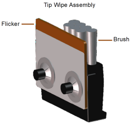
Once material is purged from a tip, the flicker portion of the tip wipe assembly passes across the tip’s opening, cutting purged material off in small segments. The brush portion of the tip wipe assembly then passes across the tip’s opening cleaning the tip and its tip shield. As a result, the flicker will wear at the location where the tip contacts its surface and eventually develop a notch large enough for the tip to completely pass through the flicker; a notched flicker cannot properly cut purging material. Similarly, material can become embedded within the bristles of the brush resulting in clumping; clumped bristles cannot properly clean a tip or its tip shield. The tip wipe assembly should be replaced once a significant notch develops within the flicker portion of the assembly or whenever bristle clumping (which cannot be removed with a brush) is apparent within the brush portion of the assembly. The tip wipe assembly is replaced as a single unit.
To clean the tip wipe assembly and inspect its components:
1.Ensure that the printer is stopped (idle) and is not building.
|
|
Caution: Depending on how long the oven has been allowed to cool, components may be hot. Wear the safety gloves provided in the Welcome Kit to perform all remaining steps. |

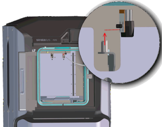
3.Remove the model side tip wipe assembly by lifting it upward until it clears its locating pins.
Figure 19: Tip Wipe Assembly Removal
4.Repeat step 3 above to remove the support side tip wipe assembly.
|
|
If the head is positioned above the purge area it may impede your ability to remove the tip wipe assemblies. Open the top cover and manually move the head away from the purge area. |
5.Clean and inspect the surface around the locating pins. Make sure that the tip wipe assemblies can sit flush on the surface.
6.Inspect the flicker portion of the tip wipe assemblies. The top edge of the flicker should be straight and must not contain excessive notching/wear.
7.Inspect the brush portion of the tip wipe assemblies. Brush bristles must not show evidence of wear (i.e. no notches in bristle pattern) and should not contain significant bristle clumping. Frayed bristles are acceptable as long as the top edge is even across all of the bristles.
8.Replace one or both of the tip wipe assemblies if excessive wear is present. See Table 2 (page 11) for information on ordering replacement assemblies.
|
|
The components of the assembly cannot be replaced individually. The entire tip wipe assembly must be replaced if excessive wear is present on the flicker or the brush. |
Figure 20: Tip Wipe Assembly Details
9.Reinstall the support side tip wipe assembly by placing the assembly onto its locating pins and sliding the assembly downward.
10.Repeat step 9 above to reinstall the model side tip wipe assembly.
Cleaning the Exterior Surface of the Printer
The printer’s exterior surfaces (doors and panels) may accumulate dust and periodically require cleaning. Exterior doors and panels, with the exception of the touchscreen display, can be cleaned using a slightly damp microfiber cloth (supplied in the Welcome Kit). The cloth should be only slightly damp to ensure that water does not enter the printer. Excess water can cause damage to interior components.
Cleaning the Touchscreen Display
|
|
Caution: Using a cleaner which contains ammonia and/or alcohol can damage the touchscreen. Only a suitable LCD cleaning solution and microfiber cloth (included in the Welcome Kit) should be used to clean the touchscreen display. |
As needed, to remove smudge marks and buildup, clean the touchscreen display using the LCD cleaner and microfiber cloth provided in the Welcome Kit.
Apply an adequate amount of LCD cleaning solution to the provided microfiber cloth and then gently wipe the exterior surface of the touchscreen display to clean its surface. It is recommended that you apply LCD cleaner to the microfiber cloth rather than applying cleaner directly to the touchscreen display, as excess moisture may damage the display.
Inspecting and Cleaning the Tip Shields
The tip shields may accumulate purged material or debris. As required, this material can be removed by manually wiping the tip shields with a clean cloth.
|
|
When printing with TPU 92A material, it is recommended to make sure that the tips and tip wipes are clean and free of debris before starting a part build. |
Cleaning the Oven Door Glass Surfaces
Required Tools
•2.5 mm hex wrench
Accessing the Oven Door Glass
1.Power off the printer. See “Powering Off” (page 17).
2.Allow the oven to cool.
3.Open the oven door.
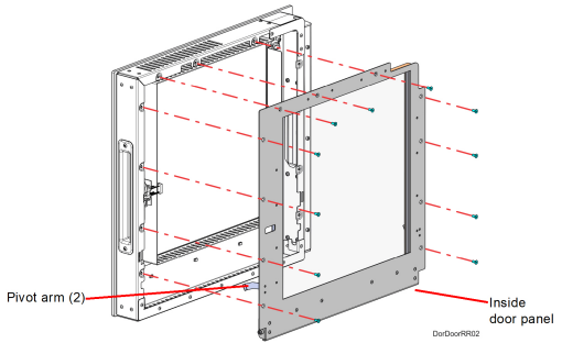
4.Using a 2.5 mm hex wrench, remove the inside door panel mounting screws (11). See Figure 50 (page 43).
Figure 21: Inside door panel mounting screw locations
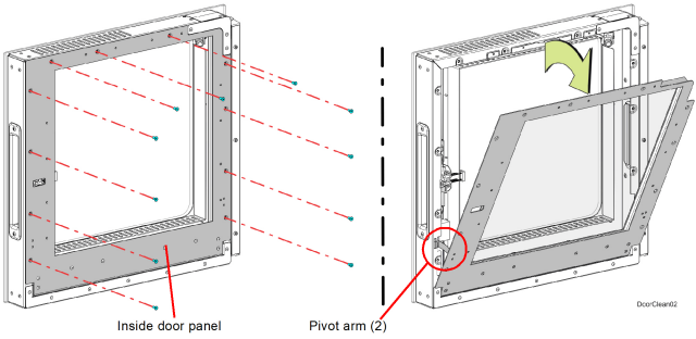
5.Pivot the inside door panel away from the door assembly. The pivot arms will prevent the door panel from fully separating. See Figure 21.
6.Clean the glass surfaces with a commercial glass cleaner.
Installing the Door Panel
1.Push the top of the door panel toward the door assembly.
2.Close the door panel and make sure that the panel and frame mounting holes are aligned.
3.Using a 2.5 mm hex wrench, install the inside door panel mounting screws (11). See Figure 21.
|
|
Do not over-tighten the inside door panel mounting screws. |
4.Close the oven door.
The following service procedures outline the replacement instructions for the customer replaceable units of the F123 Series printers.
|
|
Warning: Electrical Shock Hazard. Power OFF the printer and disconnect the power cord before replacing any of the customer replacement units. |
1.Depress the Power button (see Figure 1 (page 1) for button location).
2.Press Accept on the touchscreen display.
3.Wait approximately 25 seconds for the printer to power down.
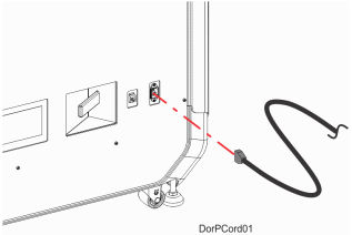
4.Remove the AC power cord from the rear of the system.
Figure 22: AC power cord location
Required Tools
•3 mm hex wrench
|
|
Removal of the rear panel requires the removal of the AC power cord. Do not install the AC power cord with the back panel removed. |
1.Power OFF the printer, see “Powering Off” (page 17).
2.Using a 3 mm hex wrench, remove the rear panel mounting screws (16). See Figure 23.
3.The rear panel has brackets that allow it to hang on the printer frame. Remove the rear panel by lifting upward and pulling away from the printer.
Figure 23: Rear Panel Mounting Screw Locations
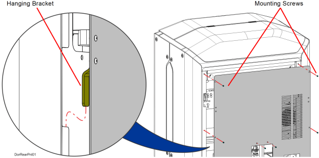
1.Insert the rear panel hanger brackets into the notches in the side panels. See Figure 23.
2.Align the rear panel with the mounting holes in the frame. See Figure 23.
3.Using a 3 mm hex wrench, loosely install the rear panel mounting screws (16). See Figure 23.
4.Tighten the rear panel mounting screws (16).
Required Tools
•5 mm hex wrench
1.Power OFF the printer, see “Powering Off” (page 17).
2.Remove the rear panel. See “Removing the Rear Panel” (page 18).
3.Using a 5 mm hex wrench, remove the side panel mounting screws (6 on each panel). See Figure 24.
Figure 24: Side Panel Mounting Screw Locations
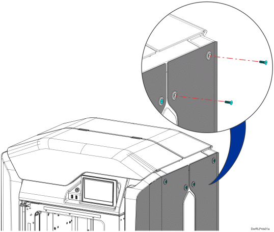
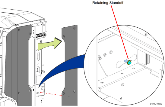
4.Rear side panels only: The rear side panels are held in place by a standoff that is retained inside the printer frame. Slide the panel away from the printer to disengage the retaining standoff. See Figure 25.
Figure 25: Rear Side Panel Retaining Standoff Detail
5.Remove the side panel from the printer.
1.Insert the side panel retaining standoff into the hole in the printer frame and slide the panel into place until it aligns with the mounting screw holes. See Figure 25.
2.Use a 5 mm hex wrench to reinstall the mounting screws (6). See Figure 24.
Required Tools
•2 mm hex wrench
1.Power OFF the printer. See “Powering Off” (page 17).
2.Open the oven door to release the front top cover latch.
3.Open the front top cover.
4.Using a 2 mm hex wrench, remove the hinge mounting screws (4) from the crossbar. See Figure 26.
Figure 26: Front Top Cover Hinge Mounting Screw Locations
5.Lift the front top cover up and away from printer to remove.
Installing the Front Top Cover
1.Align the front top cover hinges with the mounting locations on the crossbar. See Figure 26.
2.Using a 2mm hex wrench, reinstall the hinge mounting screws (4). See Figure 26.
3.Close the front top cover.
Required Tools
•2.5 mm hex wrench
1.Power OFF the printer. See “Powering Off” (page 17).
2.Open the oven door to release the top cover latch.
3.Open the front top cover.
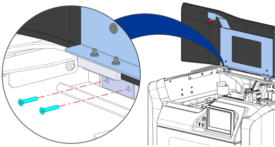
4.Using a 2.5 mm hex wrench, remove the screws (2) that secure the rear top cover to the cross bar.
5.Slide the rear top cover back and remove it from the printer. See Figure 27.
Figure 27: Rear top cover removal
1.Align the rear top cover with its mounting holes (2) in the cross bar.
2.Using a 2.5 mm hex wrench, install the screws (2) that secure the rear top cover to the cross bar. See Figure 27.
3.Close the front top cover.
4.Close the oven door.
Required Tools
•3mm hex wrench
Removing the 3.3/5/12 VDC ATX Power Supply
1.Power OFF the printer, see “Powering Off” (page 17).
2.Remove the rear panel, see “Removing the Rear Panel” (page 18).
3.Disconnect the input power cable from the power supply.
4.Disconnect the power supply cables from the I/O board (J16, J19, J20, J29).
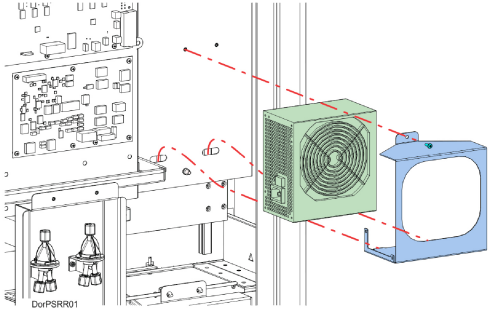
5.Using a 3mm hex wrench, remove the power supply bracket mounting screw. See Figure 28.
6.Pivot and lift the bracket slightly to remove the power supply from the electronics bay.
7.Remove the power supply from the bracket.
Figure 28: 3.3/5/12 VDC ATX Power Supply Mounting Location
Installing the 3.3/5/12 VDC ATX Power Supply
1.Transfer the mounting bracket to the new power supply.
2.Insert the bottom tabs of the power supply bracket into the slotted holes of the electronics bay panel. Pivot the power supply to its mounting orientation.
3.Use a 3mm hex wrench to reinstall the single mounting screw on top of the power supply bracket.
4.Connect the power supply cables to the I/O board (J16, J19, J20, J29).
5.Reconnect the input power cable to the 3.3/5/12 VDC ATX power supply.
6.Make sure that the switch on the power supply is in the ON position.
7.Reinstall the rear panel. See “Installing the Rear Panel” (page 18).
Required Tools
•3 mm hex wrench
Removing the Oven Thermistor
1.Power OFF the printer. See “Powering Off” (page 17).
2.Remove the rear panel. See “Removing the Rear Panel” (page 18).
3.Remove the right rear side panel. See “Right and Left Side Panels” (page 19).
4.Disconnect the thermistor cable from the I/O board (J36).
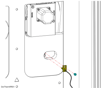
5.Use a 3mm hex wrench to remove the mounting screw (1) that secures the thermistor to the oven wall. See Figure 29.
6.Remove the thermistor from the printer. See Figure 29.
Installing the Oven Thermistor
1.Align the oven thermistor with its mounting location and use a 3 mm hex wrench to reinstall the mounting screw (1). See Figure 29.
2.Route the oven thermistor wire through the printer and reconnect it to the I/O board (J36).
3.Reinstall the right rear side panel. See “Installing the Side Panels” (page 20).
4.Reinstall the rear panel. See “Installing the Rear Panel” (page 18).
Required Tools
•2.5 mm hex wrench
•3 mm hex wrench
1.Unload material. See “Unloading Material” (page 7).
2.Open the material bay drawer.
3.Unlatch and open the material bay lid.
4.Remove the existing material spool from the material bay.
5.Place the used material spool into an airtight bag and seal it.
6.Close the material bay lid.
7.Close the material bay drawer.
8.Power OFF the printer. See “Powering Off” (page 17).
9.Remove the rear panel. See “Removing the Rear Panel” (page 18).
10.From the rear of the corresponding material bay, press and hold the locking tab to release the material tube.
11.Disconnect the material tube from the material bay and release the locking tab. See Figure 30.
Figure 30: Disconnecting material tube
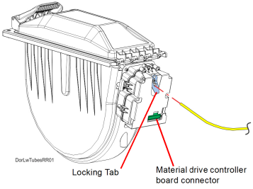
12.Disconnect the cable from the material drive controller board connector. See Figure 30.
13.Open the material bay drawer.
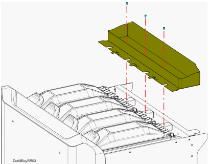
14.Using a 3mm hex wrench, remove the screws (3) that secure the rear tool tray. Remove the rear tool tray.
Figure 31: Rear tool tray
15.Using a 2.5mm hex wrench, remove the material bay mounting screws (2). See Figure 32.
16.Gently tilt and lift the material bay to remove it from the open drawer. See Figure 32.
|
|
Caution: Be careful not to damage the spool interface board on the side of the material bay. |
Figure 32: Material Bay Removal
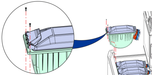
1.Gently install the material bay to the open drawer. See Figure 32.
2.Using a 2.5mm hex wrench, fasten the mounting screws securing the material bay to the top of the drawer. See Figure 32.
3.Close the material bay drawer.
4.From the back of the printer, connect the cable to the material drive controller board connector. See Figure 30 (page 25).
5.Press and hold the locking tab to install the filament tube to the rear of the material bay. See Figure 30 (page 25).
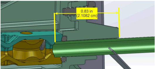
|
|
Make sure that there is 0.83 inch of tube from the tube support finger to the bottom of the switch block assembly. See Figure 33. |
Figure 33: Correct material bay material tube installation
6.Open the material bay drawer and view the filament tube from the rear of the printer. Make sure that the filament tube is routed properly with no interference.
7.Install the rear tool tray.
8.Install the material spool to the material bay.
9.Close and latch the material bay.
10.Close the material bay drawer.
11.Install the rear panel. See “Installing the Rear Panel” (page 18).
12.Power ON the printer. See “Powering ON the Printer” (page 1).
13.Load material. See “Loading Material” (page 3).
When a head reaches the 1500 build hour odometer limit (800 hours for a TPU 92A head or 700 hours for an ABS-CF10 head), a warning will be displayed on the User Interface and the head’s Head Status Icon will be highlighted in red on the Materials page. You can continue using a head which has exceeded its odometer limit, but it is highly recommended that you change the head as part quality will be unpredictable. See “Replacing a Head” (page 12) for instructions on replacing a head. Replacing an ABS-CF10 head is the same as replacing a standard head.
The process for replacing a PLA head varies slightly from the process for replacing a standard head. When building with PLA material a specialized PLA head is used. The PLA head must be installed into the model head location within the gantry. A cooling module is used in conjunction with the PLA model head and must be installed into the support head location within the gantry. The PLA model head extrudes both model and support materials. See “Replacing a PLA Head” (page 14) for instructions on replacing a PLA head or the associated cooling module.
Required Tools
•3 mm hex wrench
Removing the Head Ribbon Cables
|
|
Make sure to disconnect the head ribbon cables while the printer is powered ON to ensure that auto-calibration occurs after re-installation. |
1.With the printer powered ON, open the top cover.
2.Move the X bridge to the front of the gantry enclosure.
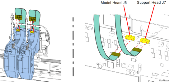
3.Disconnect the head ribbon cable connectors (2) from the tops of the material and support heads. See Figure 34 (page 29).
4.Power OFF the printer.
5.Remove the rear panel. See “Removing the Rear Panel” (page 18).
6.Disconnect the head ribbon cable connectors (2) from the I/O board (J6 and J7). See Figure 34.
Figure 34: Head Ribbon Cable Connections
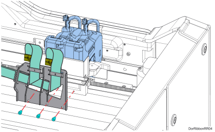
7.Using a 3 mm hex wrench, remove the front ribbon cable bracket mounting screws (3) on the back of the toggle assembly. Retain the screws for re-installation. See Figure 35.
Figure 35: Front Ribbon Cable Bracket Mounting Screw Locations
8.Lift and disengage the rear ribbon cable bracket from the back, top of the printer frame. See Figure 36.
Figure 36: Rear Ribbon Cable Bracket Mounting Detail
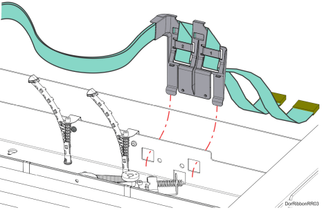
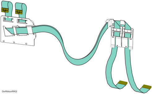
9.Remove the head ribbon cables and cable brackets from the printer. See Figure 37.
Figure 37: Head Ribbon Cables and Brackets
Installing the Head Ribbon Cables
1.Install the rear ribbon cable bracket to cutouts at the back, top of the printer frame. See Figure 36 (page 30).
2.Using a 3 mm hex wrench install the mounting screws (3) to fasten the front ribbon cable bracket to the back of the toggle assembly. See Figure 35 (page 29).
3.Connect the rear head ribbon cable connectors (2) to the I/O board (J6 and J7). See Figure 34 (page 29).
4.Connect the front head ribbon cable connectors (2) to the material and support heads. See Figure 34 (page 29).
5.Install the rear panel. See “Installing the Rear Panel” (page 18).
6.Close the top cover.
Required Tools
•3 mm hex wrench
Removing the Touchscreen Display
|
|
Caution: The connectors and cables of the touchscreen display are fragile. Excessive force may cause damage to connector pins or wiring. |
1.Power OFF the printer. See “Powering Off” (page 17).
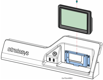
2.Using a 3 mm hex wrench, remove the mounting screw (1) that secures the touchscreen to the display panel bracket. See Figure 38 (page 32).
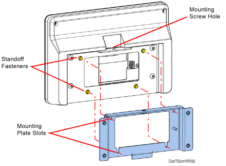
3.Gently lift the touchscreen slightly to disengage the standoff fasteners (4) from the display panel bracket. See Figure 38 (page 32).
4.While supporting the touchscreen, tilt it away from the bracket to disconnect the touch extender cable and the display cable from the back of the display.
|
|
The flat display cable connector is fragile. Simultaneously pull both corners of the connector straight out, without rocking back and forth. |
5.Gently move the touchscreen away to remove it from the printer. See Figure 38.
Figure 38: Touchscreen Mounting Screw Location
Installing the Touchscreen Display
1.Reconnect the touch extender cable and the display cable to the back of the touchscreen display.
|
|
Orient the shiny side of the connector away from the display. The flat display cable connector is fragile. Simultaneously push both corners of the connector straight in, without rocking back and forth. |
2.Align the touchscreen’s standoff fasteners (4) with the corresponding slots in the mounting plate and gently press it down until it is fully seated. See Figure 39.
|
|
If all four of the standoff fasteners are not properly installed, the mounting screw holes on top of the brackets will not align. |
Figure 39: Mounting Plate Slots and Alignment
3.Use a 3 mm hex wrench to reinstall the touchscreen mounting screw (1). See Figure 38.
|
|
Touchscreen calibration should be performed after proper touchscreen operation is confirmed. See “Touchscreen Calibration” (page 13). |
Right and Left Side Oven Blowers
Required Tools
•2.5 mm hex wrench
•3 mm hex wrench
1.Power OFF the printer. See “Powering Off” (page 17).
2.Remove the rear panel. See “Removing the Rear Panel” (page 18).
3.Remove the side panels. See “Right and Left Side Panels” (page 19).
4.Right-side oven blower only: Using a 2.5 mm hex wrench, remove the mounting screws (2) that secure the center side bezel and remove it from the printer.
Figure 40: Center Side Bezel Mounting Screw Locations
5.Disconnect the oven blower motor connector from the I/O board (J39 - right blower, J37 - left blower).
|
|
Take note of the wire routing configuration for ease of installation. |
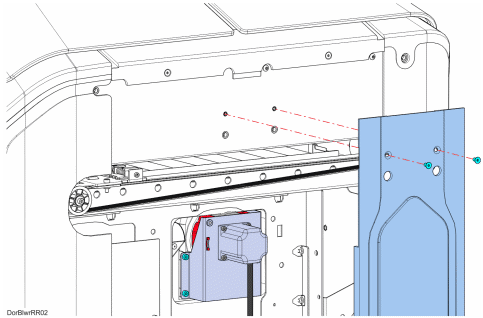
6.Using a 3 mm hex wrench, remove the mounting screws (5) that secure the blower assembly to the oven frame, see Figure 41.
7.Remove the blower assembly from the printer. See Figure 41.
|
|
Right side oven blower shown only. The left side blower procedure is identical to the right. |
Figure 41: Right Side Blower Assembly Mounting Screw Locations

Installing the Oven Blower Assembly
1.Using a 3 mm hex wrench, reinstall the blower assembly mounting screws (5). See Figure 41.
2.Make sure the blower motor cable is routed properly and secured with tie wraps.
3.Reconnect the fan blower motor cable connector to the I/O board (J39 - right blower,
J37 - left blower).
4.Right-side oven blower only: Using a 2.5 mm hex wrench, reinstall the mounting screws (2) that secure the side bezel to the printer.
5.Reinstall the side panels. See “Installing the Side Panels” (page 20).
6.Reinstall the rear panel. See “Installing the Rear Panel” (page 18).
Required Tools
•Screwdriver or similar instrument
Removing the Oven Door Gasket
1.Power OFF the printer. See “Powering Off” (page 17).
2.Open the oven door.
3.Extract the gasket pins out of the holes around the entrance to the oven enclosure. See Figure 42.
4.Pull the ends of the gasket out of the hole below the entrance to the oven enclosure. See Figure 42.
5.Remove the oven gasket from the printer.
Figure 42: Oven Door Gasket Detail (door removed for clarity)
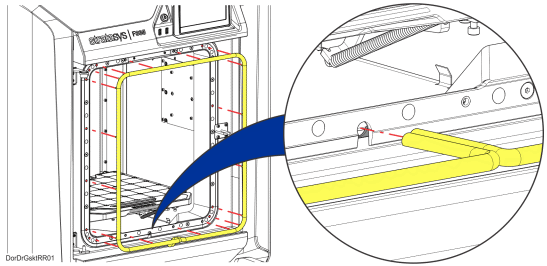
Installing the Oven Door Gasket
1.Insert the gasket pins into the holes around the perimeter of the entrance to the oven enclosure.
2.Use a screwdriver or similar instrument to poke the ends of the gasket into the hole below the entrance to the oven enclosure.
3.Close the oven door.
Required Tools
•3 mm hex wrench
•Small flat head screwdriver
1.Power OFF the Printer. See “Powering Off” (page 17).
2.Remove the rear top cover. See “Removing the Rear Top Cover” (page 21).
3.From inside the gantry enclosure, Use a 3 mm hex wrench to loosen the Z motor mounting screws (4). See Figure 43.
Figure 43: Z Motor Mounting Screw Locations
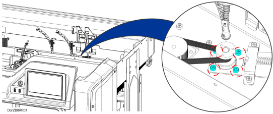
4.Using a small flat head screwdriver, relax the belt tension by gently prying the Z motor tension bracket away from the compression spring. See Figure 44.
Figure 44: Relaxing Z Belt Tension
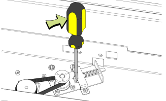
5.While the belt tension is relaxed, remove the Z drive belt from its pulleys and extract it from the printer.
1.Using a small flat head screwdriver, relax the belt tension by gently prying the Z motor tension bracket away from the compression spring. See Figure 44 (page 37).
2.Install the Z drive belt to the Z motor pulley.
3.Install the Z drive belt to the Z axis lead screw pulley.
4.Remove the flat head screwdriver from the tension bracket to restore proper tension to the Z belt.
5.Rotate the lead screw pulley two revolutions to align the Z drive belt on both pulleys.
6.Using a 3mm hex wrench, tighten the Z motor mounting screws (4). See Figure 43 (page 37).
7.Reinstall the rear top cover. See “Installing the Rear Top Cover” (page 22).
8.Close the front top cover.
Required Tools
•3 mm hex wrench
1.Power OFF the printer.
2.Open the front top cover.
|
|
Move the X bridge as necessary to access Y bellows mounting clips and screws. |
3.Remove the front Y bellows assembly. See Figure 45 (page 39).
a.Remove the clips (4) that secure the front bellows retainer to the front of the oven frame.
b.Remove the clips (4) that secure the front bellows retainer to the front of the X bridge assembly tray.
c.Remove the front Y bellows and retainers from the gantry enclosure.
d.Retain the Y bellows retainers for re-installation.
4.Remove the back Y bellows assembly. See Figure 45 (page 39).
a.Remove the clips (4) that secure the back bellows retainer to the rear of the oven frame.
b.Using a 3 mm hex wrench, remove the screws (3) that secure the back bellows retainer to the back of the X bridge assembly tray.
c.Remove the back Y bellows and retainers from the gantry enclosure.
d.Retain the Y bellows retainers for re-installation.
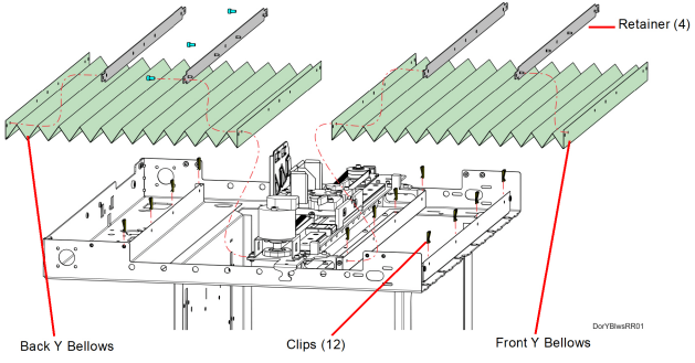
1.Transfer the Y bellows retainers to the new Y bellows.
2.Move the X bridge to the front of the gantry enclosure.
3.Install the front and rear clips (8) that secure the front Y bellows assembly to the X bridge and oven frame. See Figure 45.
4.Install the rear clips (4) that secure the back Y bellows assembly to the rear of the oven frame. See Figure 45.
5.Using a 3 mm hex wrench, install the screws (3) that secure the back bellows retainer to the back of the X bridge assembly tray. See Figure 45.
Required Tools
•3 mm hex wrench
•Small flathead screwdriver
Removing the Oven Light
1.Power OFF the printer. See “Powering Off” (page 17).
2.Open the oven door.
3.Remove the top gasket pins on both sides of the oven light above the oven enclosure. Temporarily displace the top of the oven door gasket to access the oven light.
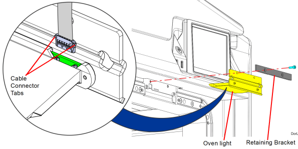
4.Using a 3mm hex wrench, remove the oven light mounting screws (2) and the retaining bracket. See Figure 46.
5.Move the oven light out a small distance to access the oven light cable connector.
6.Disconnect the oven light cable connector and remove it from the printer. If necessary, use a small flathead screwdriver to disengage the cable connector tabs. See Figure 46.
Installing the Oven Light
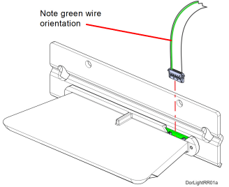
1.Connect the loose cable connector to the oven light. Orient the cable with the green wire toward the center of the light. See Figure 47.
Figure 47: Oven Light Cable Detail
2.Tuck the excess cable into the bezel opening and push the oven light into its mounting position. If necessary, pull the cable from inside the gantry to remove slack.
3.Insert the oven light into the opening above the oven enclosure.
4.Using a 3mm hex wrench, install the retaining bracket and oven light mounting screws (2). See Figure 46 (page 40).
5.Reinstall the top gasket pins on both sides of the oven light.
6.Close the oven door.
7.Power ON the printer.
Required Tools
•3 mm hex wrench
Removing the Oven Door Camera
|
|
Do not touch the camera lens. If necessary, wipe the camera lens with a clean microfiber cloth. |
1.Power OFF the printer. See “Powering Off” (page 17).
2.Open the oven door.
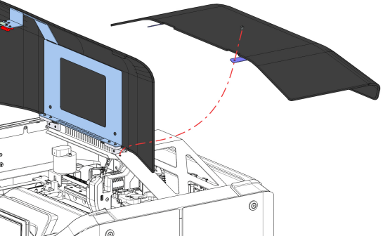
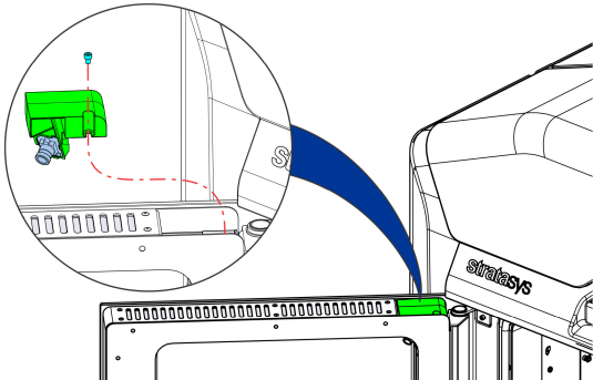
3.Using a 3mm hex wrench, remove the camera assembly mounting screw (1) through the hole in the top of the oven door. See Figure 48 (page 42).
4.Gently move the camera assembly out a small distance and disconnect the cable on the back of the camera.
5.Remove the camera assembly from printer. See Figure 48.
Figure 48: Camera Assembly Mounting Screw Location
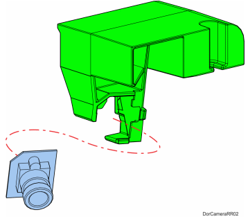
6.Carefully remove the camera from the mounting bracket. Retain the mounting bracket. See Figure 49.
Installing the Oven Door Camera
|
|
Do not touch the camera lens. If necessary, wipe the camera lens with a clean microfiber cloth. |
1.Install the camera to the mounting bracket. See Figure 49 (page 42).
2.Connect the camera cable to the connector on the back of the camera.
3.Using a 3mm hex wrench, install the mounting screw through the hole in the top of the oven door to secure the camera assembly. See Figure 48 (page 42).
Required Tools
•2.5 mm hex wrench
•4 mm socket wrench
1.Power off the printer. See “Powering Off” (page 17).
2.Open the oven door.
3.Using a 2.5 mm hex wrench, remove the inside door panel mounting screws (11). See Figure 50.
4.Pivot and remove the inside door panel from the door assembly. Gently press on the pivot arms to disengage them from the door assembly. See Figure 50.
Figure 50: Inside door panel mounting screw locations
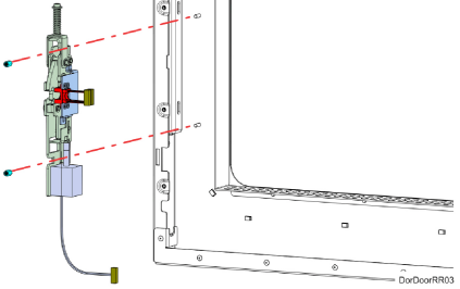
5.Disconnect the door latch assembly solenoid cable connector.
6.Disconnect the door latch assembly sensor cable connectors (2).
7.Using a 4 mm socket wrench, remove the door latch assembly mounting nuts (2). See Figure 51.
8.Remove the door latch assembly from the oven door. See Figure 51.
Figure 51: Door latch assembly mounting nut locations
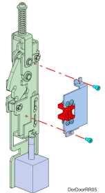
9.Using a 2.5 mm hex wrench, remove the sensor bracket mounting screws (2). See Figure 52.
10.Remove the sensor and bracket from the latch assembly and retain them for re-installation. See Figure 52.
Figure 52: Door latch sensor mounting bracket detail
Installing the Oven Door Latch
1.Using a 2.5 mm hex wrench, install the sensor bracket mounting screws (2) to secure the sensor mounting bracket to the oven door latch assembly. See Figure 52 (page 44).
2.Using a 4 mm socket wrench, install the door latch assembly mounting nuts (2) to secure the door latch assembly inside the oven door assembly. See Figure 51 (page 44).
3.Connect the door latch assembly sensor cable connectors (2).
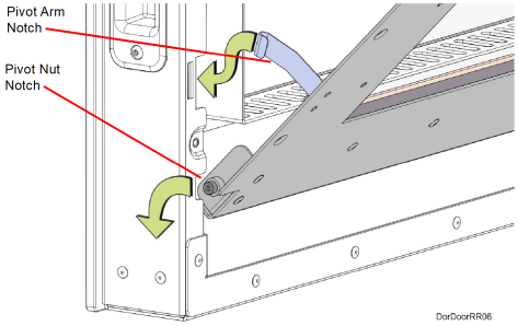
4.Install the inside door panel into the door assembly. See Figure 53.
a.Angle the inside door panel slightly and insert the pivot nuts into the lower notches on both sides of the door frame.
b.Gently press down on the door panel until the pivot nuts are fully seated inside the door frame.
c.Rotate the top of door panel toward the door assembly. Gently press in the pivot arms to insert them into the upper notches on both sides of the door frame.
d.Close the door panel and make sure that the panel and frame mounting holes are aligned.
Figure 53: Inside oven door panel detail
5.Using a 2.5 mm hex wrench, install the inside door panel mounting screws (11). See Figure 50 (page 43).
6.Close the oven door.
Required Tools
•3 mm hex wrench
Removal Procedure
|
|
Y block removal is the same for both Y blocks. Removal of the model material Y block is depicted in this procedure. |
1.Unload material.
2.Power OFF the printer, see “Powering Off” (page 17).
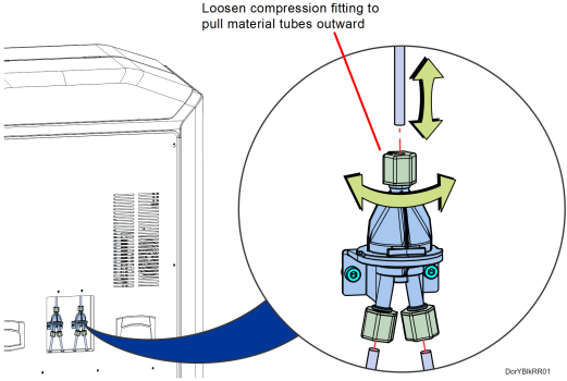
3.Disconnect material tubes at Y block by loosening the compression fittings and pulling the tubes outward. See Figure 54.
Figure 54: Disconnecting Material Tubes from Y Block
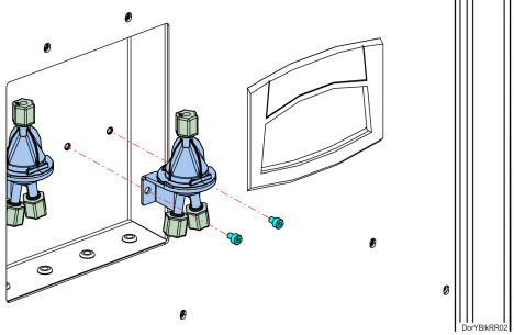
4.Using a 3 mm hex wrench, remove the Y block mounting screws (2). See Figure 55 (page 47).
5.Remove the Y block.
Figure 55: Y Block Mounting Screw Locations
Installing the Y Blocks
1.Align Y block with the mounts and use a 3 mm hex wrench to reinstall the mounting screws (2). See Figure 55.
2.Reconnect the material tubes to the Y block by pushing them through the loose compression fittings until they bottom out. Tighten the compression fittings with the tubes fully seated. See Figure 54 (page 46).
|
|
Verify that tubes are going to correct model and support connections. |
3.Power ON the printer.
4.Load material to the head from the first model and support material bays.
5.Unload material from the head.
6.Load material to the head from the second model and support material bays.
Top Cover Interlock Sensor and Actuator
Required Tools
•2 mm hex wrench
•2.5 mm hex wrench
Removing Top Cover Interlock Sensor
1.Power OFF the printer. See “Powering Off” (page 17).
2.Open the front top cover.
3.Disconnect the top cover sensor cable at the quick disconnect.
4.Remove the three cable ties that secure the cable to the sensor mounting bracket.
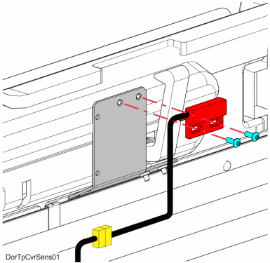
5.Use a 2 mm hex wrench to remove the sensor mounting screws (2). See Figure 56.
6.Remove the top cover sensor from the mounting bracket.
Figure 56: Top Cover Sensor Mounting Screw Locations
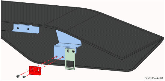
7.Use a 2.5 mm hex wrench to remove the top cover actuator mounting screws (2). See Figure 57 (page 49).
8.Remove the top cover actuator.
Figure 57: Top Cover Actuator Mounting Screw Locations
Installing the Top Cover Interlock Sensor
1.Use a 2 mm hex wrench to reinstall the mounting screws (2) that secure the interlock sensor to the mounting bracket. See Figure 56 (page 48).
2.Reconnect the top cover sensor cable at the quick disconnect connector.
3.Install three cable ties to secure the sensor cable to the mounting bracket.
4.Use a 2.5 mm hex wrench to reinstall the mounting screws (2) that secure the interlock actuator to the top cover. See Figure 57.
5.Close the top cover.
6.Power ON the printer.
7.Verify operation by opening and closing the top cover.
8.If the touchscreen displays errors indicating that the cover is not closed, adjust the position of the actuator.