This chapter describes basic calibration and adjustment procedures for the F123 Series. The buttons/pages described within this chapter are accessible via the Calibration page.
To open the Calibration page, press the Tools button within the Navigation Menu; the Tools page will be displayed (see “Working with the Tools Page” (page 38)). Within the Tools page select the Calibration button; the Calibration page will be displayed.
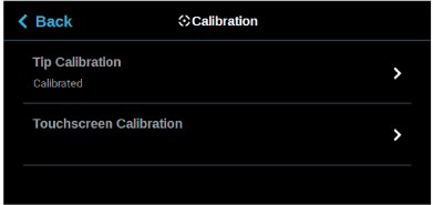
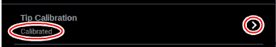
The printer’s calibration status will be displayed within the Tip Calibration row. Calibrated or Not Calibrated will be displayed depending on the printer’s calibration status.
Pressing anywhere within the Tip Calibration row will open a page allowing you to select from a variety of tip calibration options. You cannot build parts on the printer until the printer’s tips are calibrated.
Figure 2: Tip Calibration
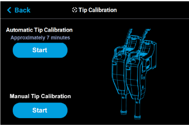
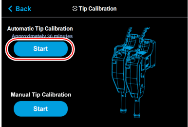
The Tip Calibration page contains an option for performing an Automatic Tip Calibration as well as a Manual Tip Calibration. Pressing the Start button associated with either of these options will allow you to perform that particular calibration procedure. Each calibration procedure is delivered in the form of a wizard which will guide you through the process of performing the calibration procedure.
Figure 3: Tip Calibration Options
Tip offset values are the distance between the model and support tips in the X, Y and Z directions. Accurate tip offset values ensure that support toolpaths are accurately located in reference to model toolpaths. Inaccurate tip offset values can cause part quality issues, such as support material embedded in a part or improperly supported parts.
Automatic Tip Calibration registers the support tip relative to the model tip, ensuring that positioning of the head and Z axis is correct when changing between model and support material during a build. This calibration is automatically performed whenever either of the printer’s heads is replaced; please note that the printer must be powered ON before calibration can occur. Calibration will occur prior to the start of the next build following the head replacement. If either head cable is unclipped and fully detached from the corresponding head, this will trigger the occurrence of an Automatic Tip Calibration. Calibration will occur following the reattachment of the cable to the head and prior to the start of the next build.
To Perform an Automatic Tip Calibration:
1.Place a new substrate onto the platen and lock the substrate into its build position by lifting up on the substrate ejection handle.
|
|
Caution: Always wear gloves when installing the substrate. Hand oils on the substrate surface will result in poor part adhesion. |

2.Open the Tip Calibration page by navigating to Tools > Calibration > Tip Calibration. A page similar to Figure 4 will be displayed.
3.Press the Start button for the Automatic Tip Calibration option.
Figure 4: Automatic Tip Calibration Option
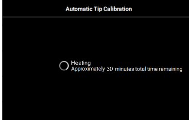
4.The printer will perform an Automatic Tip Calibration. This process includes heating up or cooling down the oven to reach the required calibration temperature. Completion times will vary depending on the material used and the initial chamber temperature. The status and time remaining will continually update on the screen.
Figure 5: Calibrating Tip Offsets
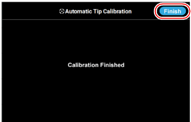
5.Completion of the calibration process will be indicated on the screen; press the Finish button within the header of the page when complete.
|
|
If calibration fails, "Failed to calibrate tip offsets" will be displayed on the screen. You cannot build a part on the printer until the tips have been calibrated. Ensure that nothing is blocking the tip or covering the calibration targets and reattempt the Automatic Tip Calibration. If calibration fails again, perform a Manual Tip Calibration (see “Manual Tip Calibration” (page 5) for instructions). |

Figure 6: Automatic Tip Calibration Complete
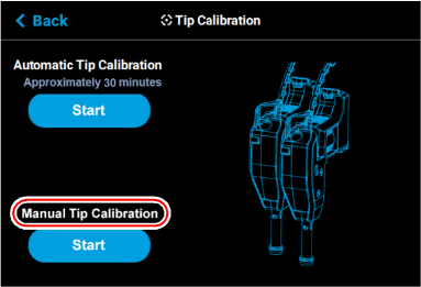
6.The main Tip Calibration page will display again. Proceed with the Manual Tip Calibration as described in “Manual Tip Calibration” (page 5).
Figure 7: Automatic Tip Calibration Option
Tip offset values are the distance between the model and support tips in the X, Y and Z directions. Accurate tip offset values ensure that support toolpaths are accurately located in reference to model toolpaths. Inaccurate tip offset values can cause part quality issues, such as support material embedded in a part or improperly supported parts.
Manual Tip Calibration sets the X, Y and Z distance between the model and support tips. This calibration requires you to analyze a calibration part once it’s built, and manually supply the printer with correction values, as needed, in order to calibrate the printer.
|
|
It is recommended to use ABS or ASA material for the manual calibration part. (PC-ABS may be difficult to remove from tray to measure the Z height). Z calibration is not needed when using TPU 92A material. The Auto Tip Calibration Z values are sufficient. |
To Perform a Manual Tip Calibration:
1.Print a calibration part; you will analyze this part in order to determine correction values.
a.Place a new substrate onto the platen and lock the substrate into its build position by lifting up on the substrate ejection handle.
|
|
Caution: Always wear gloves when installing the substrate. Hand oils on the substrate surface will result in poor part adhesion. |
b.Navigate to Tools > Calibration > Tip Calibration. Press the Start button for the Manual Tip Calibration option (see Figure 3 (page 2) for button location).
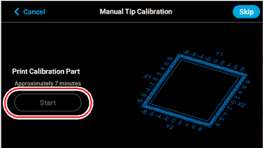
c.The Print Calibration Part page will be displayed (as shown in Figure 8) and the printer will automatically select the calibration part. Press the Start button.
Figure 8: Print Calibration Part Page
d.If your printer’s part placement setting is On (see “Part Placement” (page 44)), the Part Placement page will display. The calibration part location is fixed and can not be moved. Press the Print button (pressing the Clear button will clear the display, removing all "ghost box" items).
e.The calibration part will begin the print process and display the current status on the User Interface. "HEATING" or “COOLING” is followed by "PREPARING" and then “PRINTING“.
•The Heating/Cooling status displays the current temperature as well as the target set point.
|
|
The amount of time that the printer remains in the Heating/Cooling stage may vary depending on the current oven chamber temperature. |
•The Preparing status will display as the system purges material and detects the tray level.
•The Printing status displays the number of build layers complete or the amount of time remaining. Tap the screen to toggle between layers or time.
f.Once the calibration part is complete "DONE" will be displayed on the User Interface. Remove the substrate from the platen. You will analyze the part on the substrate to determine correction values.
|
|
After removing the substrate containing the calibration part and closing the oven door, a message is displayed stating “Is the tray ready for another job?”. Press No to return to the Manual Tip Calibration screen. |
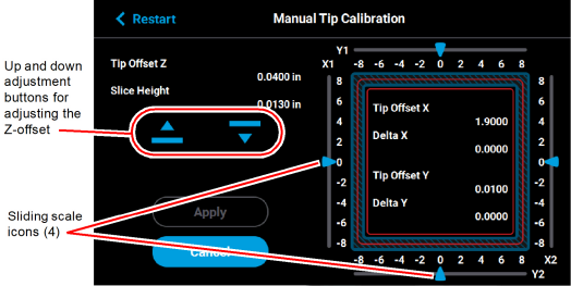
g.Press the Next button in the upper-right corner of the page; the Manual Tip Calibration page will be displayed.
Figure 9: Manual Tip Calibration Page
|
|
The Apply button will become active when you modify an offset value by dragging the sliding scale icons or pressing the up and down adjustment buttons. |
Figure 10: Apply button active

2.Determine the XY Offset Adjustment needed for your printer.
a.Using a magnifier (included in the Welcome Kit), view the relationship between the support calibration toolpath and the alignment indicators to determine the X and Y axis calibration.
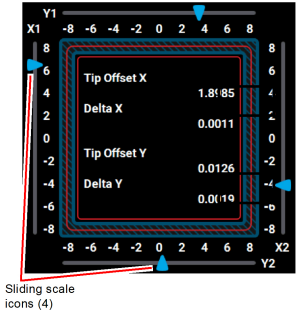
b.Determine where on each side (X1, X2, Y1, and Y2) the support toolpath is most centered between the X-Y alignment indicators (see Figure 11 or Figure 12). The numbers on the calibration part represent thousandths of an inch (e.g., 4 = 0.004 in.).
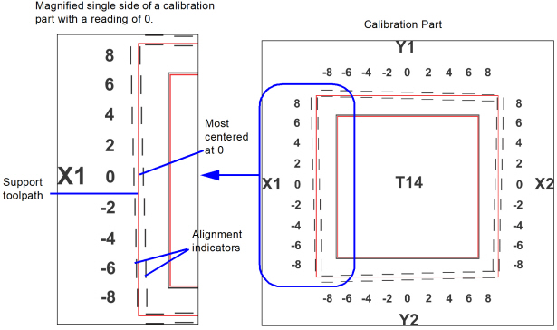
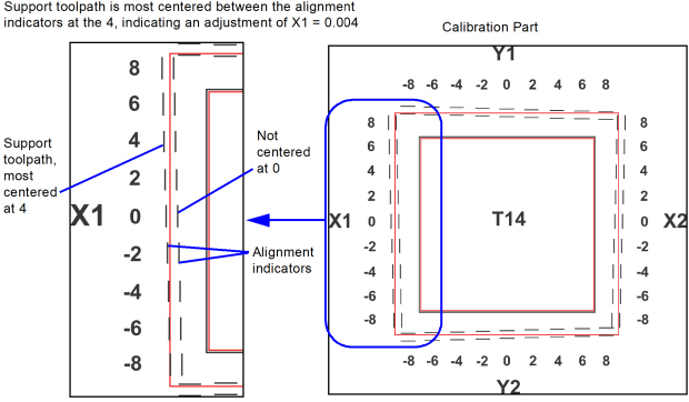
c.Within the Manual Tip Calibration page, slide all four of the scale icons on the screen to match where the support toolpath is most centered between the alignment indicators. The Delta X and Delta Y fields will change to reflect adjustments made.
|
|
One offset value must be selected for each side (X1, X2, Y1, and Y2). |
•If the Delta X and the Delta Y values are both within the range of -0.002 to +0.002 in., the printer is calibrated and an adjustment is not required. The following figure shows an XY offset within tolerance, requiring no adjustments. Proceed to step 3.
Figure 13: XY Offset - No Adjustment Required
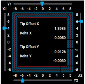
•If either of the Delta X or Delta Y values are outside the range of -0.002 to +0.002 in., the printer requires an adjustment. The following figure shows the Delta X value of 0.0050 in. and the Delta Y value of -0.0030 in. are both outside of the acceptable range.
Figure 14: XY Offset - Adjustment Required
d.If an adjustment is required, you will need to rebuild the calibration part. To do so:
•After entering your adjustment value(s) press the Apply button within the Manual Tip Calibration page (see Figure 9 (page 6) for button location). Your calibration adjustment(s) will be saved. If you continue to change the adjustment values, you must press the Apply button again to save the changes.
|
|
The Cancel button can be used to reset an adjustment value entered prior to pressing the Apply button. Once the Apply button is pressed, values will be saved and the printer’s calibration settings will reflect the adjustment value entered. Use caution when entering an adjustment value to ensure it is correct prior to pressing the Apply button. |
•After pressing the Apply button, the Close button will appear. Press the Close button to return to the initial Tip Calibration page.
Figure 15: Close Button Location

•Repeat step 1 above to build a calibration part.
•Repeat the instructions in step 2. Continue to check and adjust for XY offset. Readjust until both of the Delta X and Delta Y values are within tolerance, which is within -0.002 to +0.002 in.
e.Proceed to the Z offset adjustment (step 3 below) once the calibration toolpath for X and Y is within tolerance.
3.Determine the Z Offset Adjustment.
|
|
The Z Offset Adjustment is not needed when using TPU 92A material. |
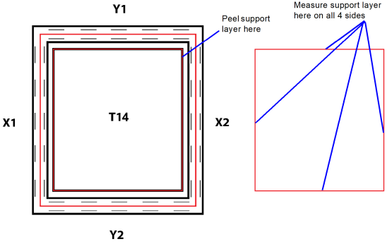
a.Peel the support layer from the inner square of the calibration part.
b.Measure the thickness of the support layer on each side of the square with a caliper or micrometer. Measure in the center of each side; measuring near the corners will result in inaccurate values.
c.Take the average value of the four measurements. This is the number you will enter for the Z offset adjustment.
Figure 16: Remove and Measure Support Layer
d.If the value measured in step c above is within ±0.0005 in. (0.01 mm) of the model tip’s slice height of 0.010 in. (0.254 mm), the printer is calibrated for the Z axis and an adjustment is not required. Proceed to step 4.
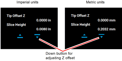
e.If the value measured in step c above is not within ±0.0005 in. (0.01 mm) of the model tip’s slice height you will need to enter a Z offset adjustment using the Up and Down buttons within the Manual Tip Calibration page. Each button press equates to one ten thousandths of an inch.
•Use the Down button to enter the value obtained in step c above if this value is less than the tip’s slice height. For example, if you measured an average of 0.0080 in. (0.2032 mm) for a tip with a slice height of 0.010 in. (0.254 mm), press the Down button until 0.0080 (0.2032) is displayed within the Slice Height field.
Figure 17: Z Offset Adjustment
•Use the Up button to enter the value obtained in step c above if this value is greater than the tip’s slice height. For example, if you measured an average of 0.0120 in. (0.3048 mm) for a tip with a slice height of 0.010 in. (0.254 mm), press the Up button until 0.0120 (0.3048) is displayed within the Slice Height field.
Figure 18: Z Offset Adjustment

f.If a Z offset adjustment is required you will need to rebuild the calibration part. To do so:
•After entering your Z offset adjustment press the Apply button within the Manual Tip Calibration page (see Figure 9 (page 6) for button location). Your calibration adjustment(s) will be saved. If you continue to change the adjustment values, you must press the Apply button again to save the changes.
|
|
The Cancel button can be used to reset an adjustment value entered prior to pressing the Apply button. Once the Apply button is pressed, values will be saved and the printer’s calibration settings will reflect the adjustment value entered. Use caution when entering an adjustment value to ensure it is correct prior to pressing the Apply button. |
•After pressing the Apply button, the Close button will appear. Press the Close button to return to the initial Tip Calibration page.
Figure 19: Close Button Location

•Repeat step 1 above to build a calibration part.
•Repeat the instructions in step 3 above. Continue to check and adjust for Z offset until the support layer matches the model tip slice height ±0.0005 in. (0.01 mm).
4.Once you’re finished adjusting for XY and Z, press the Apply button within the Manual Tip Calibration page and your calibration adjustment(s) will be saved. Press the Close button to exit the page.
|
|
A stylus pen should be used when performing this calibration to ensure precise calibration. Do not use your fingertip to perform this calibration. If a stylus pen is not available, a pencil eraser may be used. |
You have the option of recalibrating the printer’s touchscreen display. Extreme care must be taken when performing this calibration as an improperly calibrated touchscreen can lead to button accuracy issues.
To recalibrate the touchscreen:
1.Open the Calibration page by selecting the Calibration button within the Tools page.
2.Press anywhere within the Touchscreen Calibration row.
Figure 20: Touchscreen Calibration Row

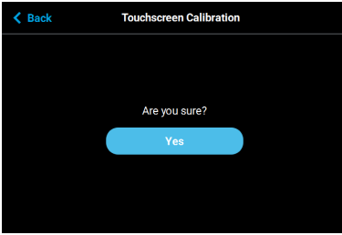
3.A dialog will be displayed asking you if you want to recalibrate the touchscreen, press the Yes button to confirm.
Figure 21: Recalibrate Touchscreen Confirmation Page
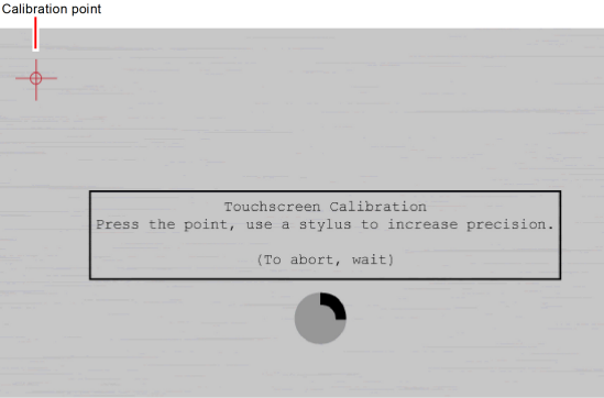
4.A dialog is displayed with instructions for recalibrating the touchscreen. Using a stylus, touch the screen in the center of the calibration point displayed. Repeat this process for the remaining calibration points (1 point for each of the 4 corners of the screen).
|
|
The graphic displayed within the center of the dialog represents the time remaining before the touchscreen calibration times out. The black portion will fill the perimeter of the gray circle in a clockwise direction. You must touch the calibration point displayed within the screen before the black portion of the graphic completes a full circle. The timer will reset for each of the 4 calibration points displayed. If you wish to exit the page without calibrating the screen simply wait until the black portion of the graphic completes a full circle; the dialog will close and you will be returned to the Calibration page. |
5.Once finished, your calibration settings will be saved and the dialog will close. You will be returned to the Calibration page.
Figure 22: Touchscreen Calibration procedure
The printer is designed to automatically perform an XY Gantry Calibration as part of its initialization and startup process. This calibration moves the gantry to ensure it can travel properly throughout the build envelope and determines the gantry’s reference in relation to the platen. Each time the printer is powered ON, it will automatically perform this calibration. The XY Gantry Calibration is responsible for finding the home position for the X and Y axes. The home position is a set location the printer references for all movements.
When performing the XY Gantry Calibration the printer will move the head at a low velocity to the full extents of travel in the X and Y axis. The homing process uses mechanical hard stops in conjunction with commanded motion control while actively monitoring servo motor following error. After XY gantry homing has completed, the extent of travel in X and Y is compared against an upper and lower limit, and an error is generated if travel is outside of those limits.
The commanded motion used to determine all four gantry hard stop locations is identical. The controller sets upper time and distance limits for each hard stop location. These limits are used to ensure hard stop engagement occurs within expected parameters.
The printer automatically initiates a Z Zero Calibration before each job is built; "PREPARING" will be displayed within the Build Status Display of the User Interface while this process is occurring (see “Build Status Display” (page 9)). Z Zero Calibration must complete successfully before a build will begin. This calibration requires no user interaction and sets the reference point between the model tip and the substrate to ensure proper positioning for the first layer of a build.
When performing the Z Zero Calibration a purge of the model tip will be performed. The head will then be positioned over the back of the platen and the Z stage will move upward until the model tip is deflected; this deflection is used to calibrate the toggle sensor. The printer will then cool the model tip to a temperature below 200°C (392°F). Once cooled, the printer will perform four tip touches, one per each of the four quadrants of the build tray, by moving the Z stage upward within that quadrant until the model tip is deflected. Z Zero positioning is then determined based on the average Z stage position of the four tip touches; the printer will set the Z Zero position.
|
|
If any of the four tip touches used to determine Z Zero is greater than 0.01” away from the average, homing will fail and the build will be aborted with a "Substrate Not Level" error. |
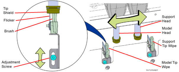
Required Tools
•3 mm hex wrench
Adjusting Tip Wipe Height
|
|
Always wear gloves when performing maintenance within the oven enclosure or other high temperature areas. |
1.Power OFF the printer. See “Powering Off” (page 17).
2.Open the front top cover.
3.Open the oven door.
4.Manually move the model head (left side) back and forth above the model tip wipe assembly (left side). Verify that the brush and flicker both make contact with the tip shield.
5.If necessary, adjust the tip wipe height.
a.Using a 3mm hex wrench, loosen the tip wipe mounting screw at the back of the oven enclosure. See Figure 23
b.Adjust the height of the tip wipe so that the tops of the brush and flicker just contact the bottom of the head tip shield.
c.Tighten the tip wipe assembly mounting screw.
d.Manually move the head back and forth to verify that the brush and flicker are contacting the tip shield without extreme resistance.
6.Repeat step 4 and step 5 above for the support head (right side) and support tip wipe assembly (right side).
|
|
Make sure that the toggle bar is in the lower position when verifying/adjusting the height of the support tip wipe assembly. |