
Aligning the Print Heads
You should check the alignment of the print heads—
|
•
|
after replacing one or more heads
|
This procedure takes about 20 minutes.
To check the alignment of the print heads:
|
•
|
a transparency sheet, A-4 or Letter size |
|
•
|
any type of adhesive tape, to fasten the transparency sheet to the build tray |
|
2.
|
Start the Head Alignment wizard from the Options menu. |
|
3.
|
Click Next to begin, and close the cover. |
|
4.
|
In the wizard screen, select the check box to confirm that the cover is closed, and click Next. |
|
5.
|
When instructed to do so, place the transparency on the build tray— next to the left and rear edges of the tray, as shown in the following figure. |
|
6.
|
Make sure that the transparency sheet is lying flat, and tape it to the tray. |
|
7.
|
In the wizard screen, select the check box to confirm that the transparency sheet is on the build tray, and click Next. |
The printer prints the head alignment test on the transparency.
|
8.
|
When the following screen appears, remove the transparency. |
The transparency sheet is printed with sets of vertical lines in seven columns, each showing the results from a different print head.
Note: There is no column for head H7 because its alignment is used as a reference for aligning all other heads.
|
9.
|
For each column of lines, use a magnifying glass or loupe to inspect pairs of consecutive rows printed on the transparency to see where the vertical lines align. |
Note: It does not matter which pair of lines you inspect, since they were all printed by the same head. Choose a pair of clearly printed lines for the inspection. (Since some nozzles may not print clearly, you may have to inspect several pairs of lines to properly view the alignment.)
Optimum head alignment is shown when the fourth lines in the upper and lower rows are aligned, as in
the figure above.
In the example shown, no change to the head alignment is necessary. If other lines in the set are aligned, you need to change the alignment of that head—in the next wizard screens.
|
10.
|
In the wizard screen, select the Transparency removed check box, and click Next. |
The first in a series of alignment screens appears.
|
11.
|
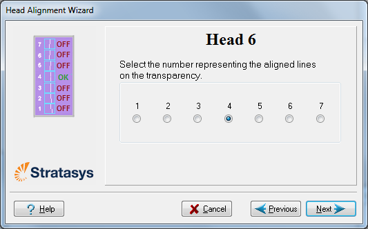
In the head-alignment screen, select the number that indicates which lines align in the upper and lower rows of a pair on the transparency (counting from the left) for this print head. |
Note: Because the alignment of the fourth lines is optimum, the number “4” is selected, by default, in the wizard screen. This does not change the head alignment. If you select other numbers, the wizard adjusts the head alignment, accordingly.
|
12.
|
Click Next to display the next head alignment screen, and again select the number representing the most closely aligned vertical lines on the transparency for that print head. |
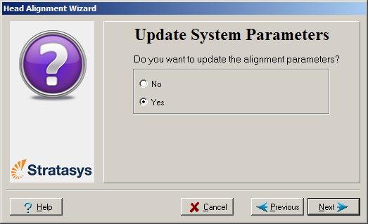
When you have finished aligning all of the heads, the following screen is displayed.
|
•
|
To make the alignment changes in the printer, make sure that Yes is selected, and click Next. |
|
•
|
To recheck the alignment test results before making the alignment changes in the printer, click Previous. |
|
•
|
If you do not want to make alignment changes in the printer at this time, select No and click Next. |
|
14.
|
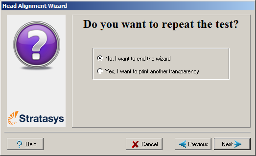
In the following screen, you can choose to either repeat the head alignment procedure or close the wizard. |
|
•
|
If the most closely aligned vertical lines for a print head were at either extreme, choose Yes to run the Head Alignment wizard again, then click Next. |
The transparency test will show if the heads are now properly aligned, and—if not—the wizard will allow you to “fine tune” the alignment.
|
•
|
If the vertical lines for the print heads were not aligned at either extreme, choose No to close the wizard, then click Next. |
 Related Topics