5
This chapter explains basic steps in operating the F120 printer
To power the printer ON:
1.Connect the male end of the supplied power cord directly into a grounded electrical outlet.
2.Connect the female end of the power cord directly into the socket located on the back of the printer (see Figure 4 (page 4) for location).
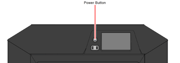
3.Press the power button located on the front of the printer.
Figure 1: Power Button Location
4.The printer will begin to boot. The touchscreen will turn on and begin initializing.
5.The first time the printer is powered ON a dialog will be displayed asking you to select your desired language. Select the radio button corresponding to your desired language by touching its row on the screen, then confirm your selection.
Figure 2: Initializing Start Up Screen

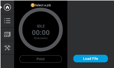
6.After the initialization and start up process is complete, the touchscreen will refresh to display the Build page and the printer will automatically perform an XY Gantry Calibration (see “XY Gantry Calibration” (page 16) for details).
Figure 3: Build Page
To power the printer OFF:
1.Ensure that the printer is stopped (idle) and is not building.
2.Press the power button located on the front of the printer (see Figure 1 for button location).
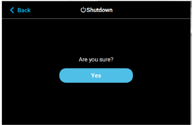
3.A dialog will be displayed asking you to confirm the power OFF; press Yes to power OFF.
Figure 4: Power OFF Confirmation
4.After a couple of minutes the printer will shutdown.
Please note that this procedure only powers down the electronics. To completely disengage power to the printer, you must unplug the power cord located at the rear of the printer.
|
|
For extended non-use periods greater than 72 hours, unload the material, store the material in an air tight bag and power OFF the system. |

The information within this section will walk you through the process of loading material to the model and support heads. As you complete the required steps, be sure to observe the status information displayed on the touchscreen.
|
|
Caution: If the printer remains idle for more than 72 hours, leaving material in the filament tubes could result in a part quality issues due to wet filament. failed build. To prevent this: •Remove filament from the tubes. Or •Unload filament and cut six feet of material from the material coil box. |

|
|
Loading material can only be done when the printer is stopped (idle) and is not building. |
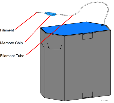
The “Material Coil Box Preparation” (page 3) section describes the steps necessary to prepare a material coil box for use, and highlights the components of the material coil box. Once a material coil box has been prepared for use, the steps within the “Connecting Material Coil Box To Printer” section will guide you through the process of connecting a material coil box and loading material to the head.
Two material coil boxes, one for model and one for support, must be connected to the F120 in order for it to build.
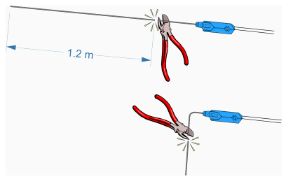
When preparing a material coil box, open the box and route the material tube and filament key through the material routing notches. Close the box. Once the filament tube and key are routed, pull the end of the filament until approximately 1.2 meters of material are outside the material tube. Cut the 1.2 meters of filament using the 5” cutter included in the Welcome Kit. This length of material is removed for moisture control. Refer to Figure 5 for material coil box details.
Figure 5: Material Coil Box Details
The material coil box is ready to be connected to the printer. Follow the steps in “Connecting Material Coil Box To Printer” (page 4) to connect the material coil box and load material to the head.
Connecting Material Coil Box To Printer
Once you’ve properly prepared a material coil box, you can begin the process of loading material. Pre-loading filament to the drive wheels places the filament into position to be loaded to the liquefier tip within the head.
To connect and load material from a material coil box:
1.Ensure that the printer is stopped (idle) and is not building.
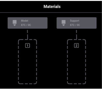
2.Select the Materials button from the Navigation Menu; a screen similar to Figure 6 (page 5) will be displayed. The information displayed represents the current configuration of your printer.
Figure 6: Current Configuration - Load Material
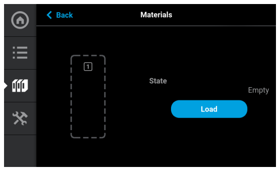
3.Click inside the grey outlined box for the material type (Model or Support) you wish to load. A screen similar to displays. Click the Load button.
Figure 7: Current Configuration - Load Model Material
4.Clicking the Load button activates the F120 Material Load Wizard. The screen below displays.
Figure 8: Load Material Wizard Screen
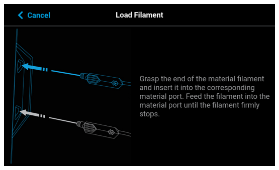
5.Grasp the end of the material filament and insert it into the corresponding material port (see Figure 9). Feed the filament into the material port until the filament firmly stops. At this point, the machine will begin to feed the material into the liquefier.
6.Material begins to load to the liquefier tip within the head. The pathway displayed between the Material Status Icon and the corresponding Head Status Icon becomes highlighted to indicate load progress (see Figure 32 (page 35)).
7.When filament reaches the head, it enters the liquefier tip and begins to warm to the material operating temperature (automatic - based on material coil box memory chip data). This step also sets the oven temperature to the correct value for the material being loaded
8.Once the tip is within three degrees of the set point temperature the head moves to the purge area and the tip purges a small amount of material.
9.Insert the filament key into the corresponding slot. While the material is loading, a screen similar to the one shown below will display.
Figure 10: Material Loading
10.When the load process is complete, a screen similar to the one shown below will display. Material is now loaded to the print head.
Figure 11: Material Loaded
|
|
Only one material can be loaded at a time. |
11.Press the Back button within the Material Details page to exit and return to the Materials page.
12.If necessary, perform this procedure for the support material
13.Once material is loaded, the filament pathway between the Material Status Icon and the corresponding Head Status Icon will be solid blue, the Head Status Icon will turn from gray to blue, and the Material Status Icon will display a solid blue border.
You are now ready to select a job to build, see “Basic Job Build Tasks” (page 16) for information on selecting and starting a job.
|
|
Caution: If the printer remains idle for more than 72 hours, leaving material in the filament tubes could result in a part quality issues due to wet filament. To prevent this: •Unload filament and cut 1.2 meters of material from the material coil box •Cut the filament approximately 5 centimeters from the end of the filament key. Bend the filament 90 degrees to prevent filament from retracting into the key. •When re-loading material, pull the end of the filament until approximately 1.2 meters of material are outside the material tube and cut the filament at this point. |
Perform the following steps to unload material:
1.Ensure that the printer is stopped (idle) and is not building.
2.Select the Materials button from the Navigation Menu; a screen similar to Figure 12 (page 12) will be displayed. The information displayed represents the current configuration of your printer.
3.Observe the status information displayed for each of the Materials Status Icons. For a loaded material, the pathway between the material’s Material Status Icon and corresponding Head Status Icon will be solid blue, the Head Status Icon will be blue, and the Material Status Icon will display a solid blue border.
Figure 12: Current Configuration - Unload Material
4.Open the Material Details page corresponding to the material you want to unload by touching its Material Status Icon on the screen.
5.Press the Unload button within the Material Details page.
Figure 13: Unload Button

|
|
Only one material can be unloaded at a time. |
6.The F120 unload material wizard initializes and material begins to unload from the head. The unload process will take several minutes; please be patient.
•The pathway displayed between the Material Status Icon and the corresponding Head Status Icon becomes highlighted to indicate unload progress (see Figure 32 (page 35)).
•The Head Status Icon will refresh and become solid gray, indicating that material is no longer loaded to the head.
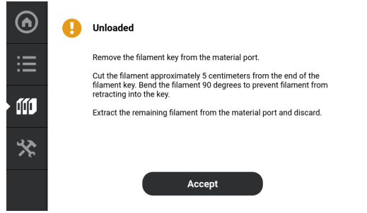
7.When the material is unloaded from the head and the F120 material unload wizard has completed its process. See Figure 15 (page 13).
•Remove the filament key from the material port.
•Cut the filament approximately 5 centimeters from the end of the filament key. Bend the filament 90 degrees to prevent filament from retracting into the key. See Figure 14 (page 13).
•Extract the remaining filament from the material port and discard.
Figure 14: Cut Filament After Unloading
8.Open the material coil box and insert the filament key and filament tube. Close the material coil box.
Figure 15: Material Unloaded Screen
At this point you have the option of loading a different material into the printer or reloading the material you just unloaded (see “Loading Material” (page 3) for detailed instructions).
|
|
Empty material coil boxes may have a small, unusable volume of material remaining. The leftover material allows for manufacturing tolerances. |
Stratasys FDM thermoplastic materials will maintain proper product performance over an extended period of time, when handled and stored according to recommended procedures. Like other thermoplastics, the filament can absorb moisture when exposed to ambient humidity. Stratasys material coil boxes are designed to minimize moisture exposure while unopened and opened. When a filament absorbs moisture a finished part's surface quality, seam quality, and overall part aesthetics can be affected. Care should be taken to ensure filament remains dry.
|
|
Caution: Material storage shall be in the range of 55°F to 86°F (13°C to 30°C), with relative humidity less than 70%. |
The model and support material coil boxes hold 200 in3 (3277 cc) of filament.
Material coil boxes also contain desiccant material; the desiccant is designed to maintain proper moisture levels within the material coil box. Once the desiccant is exposed to ambient air, it can become saturated and ineffective for moisture control. Proper handling of the material coil box is essential to maximizing material life.
When a head reaches the 1500 build hours odometer limit, a warning will be displayed on the User Interface and the head’s Head Status Icon will be highlighted in red on the Materials page. You can continue using a head which has exceeded its odometer limit, but it is highly recommended that you change the head as part quality will be unpredictable.
The information within this section is meant to guide you through the process of changing a head. Although the instructions below depict the replacement of the model head, the same procedure applies to the support head.
1.Unload material from the head that will be replaced (see “Unloading Material” (page 11) for instructions).
2.With the printer powered ON, open the top cover (see Figure 1 (page 1)).
|
|
Replacing a head while the printer is powered ON will ensure that an Automatic Tip Calibration is performed after the replacement process is compete. Power is automatically removed from the head and all motors when the top cover is opened. |
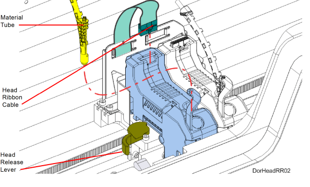
3.Depress the release tab and unclip the head ribbon cable for the head that will be replaced.
|
|
Do not twist or place rotational force on the head ribbon cable. |
4.While gripping only the connector, carefully disconnect the connector from the head.
5.Disconnect the material tube for the head that will be replaced.
6.Unlock the head release lever for the head that will be replaced.
Figure 16: Head Connections
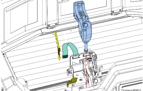
7.Pull the head assembly out of its position within the gantry and remove it from the printer.
Figure 17: Remove Head
8.Insert a new head assembly into the vacant location within the printer.
9.Lock the head into place using the head release lever. Press the lever securely closed to ensure that the head is properly seated.
10.Connect the material tube to the new head assembly.
11.Insert the head ribbon cable connector into the new head assembly ensuring it is fully seated in the head and the connector retention latch engages.
13.Perform an Automatic Tip Calibration. See “Automatic Tip Calibration” (page 2) for details. Please note that the printer must be powered ON before calibration can occur.
14.Perform a Manual Tip Calibration. See “Manual Tip Calibration” (page 5).
To build a job, you must first download job files to the printer and then load individual job files to the Job Queue using one of two methods:
1.Network transfer via the GrabCAD Print application on your workstation PC. This is the preferred method for adding jobs to the Job Queue. See “GrabCAD Print Method” (page 14) for detailed instructions.
2.USB method via a USB flash drive inserted into one of the available USB ports. See “USB Method” (page 14) for detailed instructions.
The GrabCAD Print option allows you to select a job which was processed and sent to the printer (via your facility’s Ethernet connection or via Wi-Fi) using the GrabCAD Print application on your workstation PC. Jobs are sent in CMB format and placed directly into the Job Queue (stored on the printer’s hard drive). The CMB file contains the processed job’s basic information; this information is used to verify job compatibility with the printer’s existing configuration. For information on using GrabCAD Print, see the associated Help file within the GrabCAD Print application.
The USB option allows you to select a job file which is stored on a USB flash drive inserted into one of the available USB ports (see Figure 3 (page 3) for port locations). This method can be used as a backup to the GrabCAD Print method if you are unable to transfer job files to the printer via your network connection (due to poor connectivity, a network outage, etc.) and provides a convenient option for you to reprint a common job. Alternatively, you have the option of selecting a single job file off of a USB flash drive and printing it directly within the Build page. This option is only available if the Job Queue is empty. See “Loading a File” (page 5) for details.
To prepare the printer for a build:
1.Power ON the printer (see “Powering ON the Printer” (page 1) for instructions).
|
|
Warning: Hot Surface Hazard Wear proper safety equipment when handling items inside the oven as surfaces within the oven can be very hot. |

3.Place a new substrate onto the platen and lock the substrate into its build position by lifting up on the substrate ejection handle.
|
|
Caution: Always wear gloves when installing the substrate. Hand oils on the substrate surface will result in poor part adhesion. |
|
|
Never print in the same location more than once on a substrate when building a job. |
4.Make sure that the tip wipe assembly’s brushes as well as the printer’s tips are clean and that the purge area is free of purged material debris.
1.Populate the Job Queue as described within “Before a Build” (page 16).
2.Select the Queue button within the Navigation Menu; the Queue page will open to display the Job Queue.
3.Within the Job Queue list, locate the job you’d like to build and select it by touching its row on the screen; doing so will open its Job Details page.
|
|
Jobs are built in the order in which they appear within the Job Queue. |
4.Within the Job Details page press the Print button; this will queue the job for printing. Depending on your printer’s part placement setting configuration a dialog may be displayed (see “Part Placement” (page 42)).
•If the Enable Part Placement setting is set to Off (default setting), a dialog will not be displayed and the job will automatically be built in the center of the substrate.
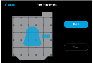
•If you set the Enable Part Placement setting to On, a dialog will be displayed allowing you to select the job’s build location (see Figure 26 (page 28)). The dialog contains a graphic representing your printer’s platen as well as a blue bounding box graphic (the imaginary box surrounding the part). Select the job’s build location by dragging and dropping the bounding box on the touchscreen. When finished, press the Print button within the dialog to confirm your selected placement and start the build.
5.The Build page will open and the oven will begin to heat to a set point temperature determined by the material types specified for the job. Please be patient.
6.After the oven and liquefier tips reach temperature the printer performs a Z Zero Calibration. "PREPARING" is displayed within the Build Status Display while this calibration occurs.
7.Once Z Zero Calibration is complete the printer begins building the job. "BUILDING" is displayed within the Build Status Display as the part is being built (see “Information Available During a Build” (page 19)).
8.When finished, text is displayed on the touchscreen indicating that the completed part can be removed from the printer (see “After a Build is Complete” (page 24)).
Information Available During a Build
During a build, information pertaining to that build is displayed within two areas of the Build page:
The Print Job Information Panel displays the details of a job, as submitted to the printer from the workstation PC. This information is static and is for reference purposes only. See “Viewing Print Job Information” (page 8) for detailed information.
Figure 18: Print Job Information Panel - Building
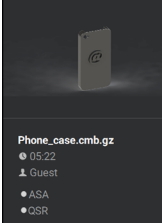
Information displayed within this panel for a selected job includes:
•Name of the job.
•Estimated build time for the job.
•Name of the user that submitted the job.
•Model and support materials associated with the job.
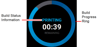
The Build Status Display section of the Build page is composed of a two-part graphic which provides information on a building job. See “Build Status Display” (page 9) for detailed information.
•The Build Status Information portion of this graphic provides information on a selected and/or building job. Text pertaining to the current status of the build is displayed within the upper portion of the graphic, while the amount of build time remaining is displayed within the lower portion of the graphic.
•The outer Build Progress Ring corresponds with the build information displayed. As build progress is made, the build’s percentage of completion is also displayed by radially filling in the outer progress ring, in blue, in a clockwise direction.
•Touching the screen within the center of the Build Status Display while a part is being built will toggle the information displayed. After touching the screen the time estimation information will be hidden from view and instead the Build Status Display will show the number of completed layers as compared to the total number of layers in the build. Touching the screen again, will toggle back to the time estimation information displayed initially.
Figure 19: Print Job Status Overview
If the printer detects an issue that may affect a build, it will be indicated within the Notifications Display portion of the “Build Page” (page 4). A yellow or red notification badge icon will be displayed, depending on the severity of the warning/error, along with text indicating the reason(s) for the warning. Touching the text on the screen will open a dialog indicating the reason(s) for the notification, and in some cases, steps to correct the notification (see Figure 4 (page 4)).
Depending on the type of warning, a notification badge icon may also be displayed within the “Material Status Icons” (page 27) of the “Materials Page” (page 21). Touching the notification badge icon on the screen will open the corresponding material’s Materials Details page and provide information indicating the cause of a warning/error.
•When loading and unloading materials you may encounter load related warnings which need to be resolved prior to starting a build.
•When starting a build you may encounter a variety of warnings pertaining to the printer’s current materials configuration. If the printer has not been calibrated, the materials installed within the printer do not match the requirements of the build, or the printer does not contain enough material to complete the build, you will receive a warning instructing you to resolve this issue.
|
|
You can choose to ignore the warning and continue the build, but part build quality will be unpredictable. A warning generated from a mis-match of model/support material cannot be bypassed. |
•In some cases, the warning will prevent you from starting a build and will need to be corrected before the printer can build a part.
•While the printer is building, various pause and abort related warnings may be displayed. Some of these warnings may be due to a manual pause or abort, while others may be the result of the printer automatically pausing or aborting a build. Depending on the severity of the warning you may or may not be able to resume building.
See “Warnings and Errors” (page 1) for a detailed list of the warnings you may encounter, and instructions on how to correct them.
During a build the Pause button within the Build page becomes selectable (see “Pause Button” (page 12) for details). The printer can pause automatically, or be manually paused using this button:
•An automatic pause occurs when a material coil box runs out of material, a failure is detected, etc.
•A manual pause occurs whenever the Pause button is pressed.
When the printer is directed to pause:
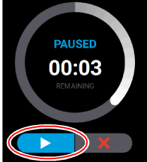
1.The current toolpath is completed, the Z stage is lowered slightly, and then the head assembly is parked. "PAUSED" is displayed within the Build Status Display (see Figure 20).
If an automatic pause occurs, text will be displayed within the Notifications Display portion of the Build Page. Touching the text on the screen will open a dialog indicating the reason for the pause condition (i.e. empty material coil box). Correct this condition and then press the Close button to exit the dialog. (See “Build Pause Warnings” (page 7) for a list of pause related warnings/errors and resolution instructions.)
2.The Pause button will toggle and instead display the Play button. To resume building, press the Play button. A resume command will be sent to the printer instructing it to resume the build (see Figure 20).
|
|
The printer will not resume building instantaneously, please be patient. |
3.Once the build resumes, "BUILDING" will be displayed within the Build Status Display and the Pause button will be displayed in its unselected state (see Table 3 (page 12)).
When the printer is building, you have the option of directly aborting the build. To do so:
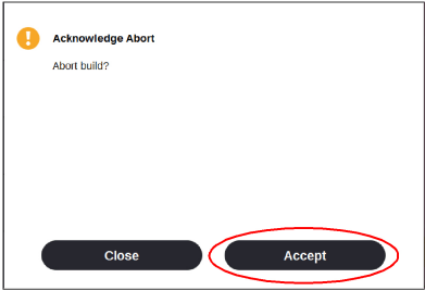
1.The Abort button within the Build page will be selectable (see “Abort Button” (page 12) for details), press the Abort button.
2.A dialog will be displayed allowing you to confirm or cancel the abort; press the Accept button within the dialog to confirm the abort.
Figure 21: Abort Confirmation Dialog
3.An abort command will be sent to the printer and the confirmation dialog will close.
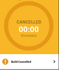
4.The Z stage will move to its end of travel. Once the Z stage reaches its end of travel the Build page will refresh and display a confirmation of the aborted build; "CANCELLED" will be displayed within the Build Status Display (see Figure 22 (page 24)).
5.The Print Job Control buttons will be hidden and instead "Build Cancelled" will be displayed within this portion of the Build page. Touching this text on the screen will open a dialog with instructions on how to remove the aborted build and prepare for your next build (see Figure 22).
Figure 22: Build Page Build Canceled
After the completion of a build, the printer performs the following actions:
•The Z stage is lowered and the head assembly is parked.
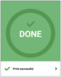
•"DONE" is displayed within the Build Status Display (Figure 23 (page 25)).
•The Print Job Control buttons will be hidden and instead "Print successful" will be displayed within this portion of the Build page. Touching this text on the screen will open a dialog with instructions on how to prepare for your next build.
•The Build button will display a green checkmark icon indicating that the build completed successfully.
|
|
If the build was terminated abnormally, a warning indicator will be displayed on the screen. See “Build Abort Errors” (page 10) for a list of abort related warnings/errors and resolution instructions. |
Figure 23: Print Successful Dialog
Removing a Part from the Printer
|
|
Warning: Hot Surface Hazard Wear proper safety equipment when handling items inside the oven as surfaces within the oven can be very hot. |
To remove a part from the printer:
1.Open the oven door.
2.Push down on the substrate ejection handle to release the substrate.
|
|
Caution: Do not attempt to remove a part from the substrate while the substrate is on the platen. Damage to the platen or platen level may occur. |
3.Remove the substrate from the platen.
4.Carefully remove the part from the substrate.
Several factory presets can be changed via the options within the Tools page. To access this page, press the Tools button within the Navigation Menu.
The options within the Tools page are organized into 6 categories: Settings, Calibration, Maintenance, Network, Power, and Light. The defaults specified within the following instructions are accessible via the Settings page. To open this page press the Settings button within the Tools page.
After making the necessary adjustments to a default setting, press the Back button in the upper-left corner of the page to exit and return to the main Settings page.
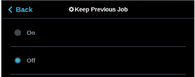
The Keep Previous Job setting determines whether or not the printer’s previous job is stored within the Job Queue once a build is complete (see “Wait for Part” (page 40)). If you're concerned about other users of your printer seeing what you’ve built, this setting will prevent the printer’s previous job from being accessible after the build is complete. By default this setting is set to On, meaning that the printer’s previous job file is stored within the Job Queue making it available for re-selection upon completion of the build.
When this setting is set to Off, the printer’s previous job file will be deleted from the Job Queue upon completion of the build. The job’s file will need to be resent to the printer in order to be built again.
To configure this setting, press anywhere within the Keep Previous Job row; the Keep Previous Job page will be displayed. Use the radio buttons within this page to turn the setting On and Off as needed.
Figure 24: Keep Previous Job
The Part Placement setting determines whether or not you can select a job’s placement on a substrate prior to starting the build (see “Part Placement” (page 42)).
To configure this setting, press anywhere within the Part Placement row; the Part Placement page will be displayed. Use the radio buttons within this page to turn the setting On and Off as needed.
Figure 25: Configure Part Placement
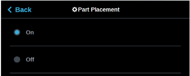
By default this setting is set to On, meaning you will be able to select a job’s location on the substrate prior to starting the build (see “Selecting a Job to Build” (page 18)). At the start of a build the Part Placement dialog will be displayed asking you to select the part’s build location (see Figure 26 (page 28)). The dialog will contain a graphic representing your printer’s platen as well as a blue bounding box graphic (the imaginary box surrounding the part). You can select the part’s build location by dragging and dropping the bounding box on the touchscreen; the bounding box cannot be placed outside the limits of the platen. Pressing the Print button will confirm your selected placement and start a build.
"Ghost box" graphics are also displayed; a "ghost box" represents the location where a part was built previously. Pressing the Clear History button will clear the display, removing all "ghost box" items.
When this setting is set to Off the Part Placement dialog will not be displayed prior to the start of a build. Single part jobs will be built in the center of a substrate while packs will be built according their selected placement within GrabCAD Print.
Figure 26: Part Placement Dialog
By default the UI is configured to display English units (inches). However, you can adjust this setting as needed to have the UI display metric units.
The Units setting determines the type of units that the printer is configured for, English or Metric. To configure this setting, press anywhere within the Units row; the Units page will be displayed. Use the radio buttons within this page to select between English and Metric units.
Figure 27: Configure Units

Oven modeling temperature is determined by the material type (model and support) loaded within the printer. It is controlled by the printer’s software and cannot be modified; however, you do have control of some oven temperature functions.
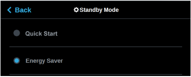
The Standby Mode setting gives the ability to put the printer into an energy saving state after the completion of a build (see “Standby Mode” (page 44)). When the Energy Saver option is selected (i.e. Standby Mode is turned On) the printer’s oven will automatically shut off 2 hours after the completion of a build, thus saving energy. When the Quick Start radio button is selected (i.e. Standby Modes is turned Off) the printer’s oven will remain On for 60 hours after the completion of a build and oven temperature will stay at the material’s build temperature.
To configure this setting, press anywhere within the Standby Mode row; the Standby Mode page will be displayed. Use the radio buttons within this page to turn the Energy Saver option On and Off.
Figure 28: Configure Standby Mode
Touchscreen Display Brightness
The Screen Brightness setting allows you to adjust the brightness of the touchscreen display (see “Screen Brightness” (page 46)). By default, the touchscreen display is configured to be at approximately 80% brightness.
To configure this setting, press anywhere within the Screen Brightness row; the Screen Brightness page will be displayed. Use the slider graphic to adjust brightness as needed; sliding to the right will increase brightness, while sliding to the left will dim brightness. Please note that you cannot set screen brightness to 0% (completely dim). After exiting the Screen Brightness page the configured brightness will be displayed as a percentage within the Screen Brightness row.
Figure 29: Adjust Screen Brightness

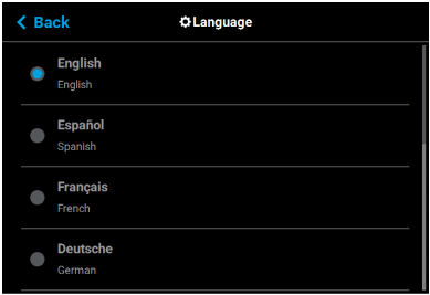
By default the text within the UI is displayed in English. However, you can adjust this setting as needed to have the UI exhibit a different language. In addition to English the display language can be set to Spanish, French, German, Italian, Russian, Chinese, and Japanese.
The Language setting determines the language that the UI is configured for. To configure this setting, press anywhere within the Language row; the Language page will be displayed. Use the scrollbar (along the right side of the page) to view the list of available languages. Select the radio button corresponding to your desired language.
Figure 30: Configure Language
The various pages of the User Interface display each of the following:
•Head odometer status
•Material status
•Temperature status
•Controller Software version
•Other printer information
The printer tracks and displays the total amount of material extruded through a head since it was last replaced. Head odometer values can be determined via the head’s Head Details page. To locate this information press the Materials button within the Navigation Menu, the Materials page will be displayed. Two “Head Status Icons” (page 22), one corresponding to the model head and the other corresponding to the support head, are displayed within the upper portion of the Display Area of the page. Touching one of these icons on the screen will open that head’s Head Details page (see “Viewing Head Details” (page 24)). Odometer information for the selected head is displayed within the right half of the Head Details page (see Figure 26 (page 25)).
The Head Status Icons can become yellow or red based on the head’s odometer (see Table 6 (page 22)). An accompanying warning/error notification will be displayed within the Materials page when a head is in a warning or error state resulting from odometer related information (see “Head Warnings” (page 12) and “Head Errors” (page 12)). An icon with yellow coloring indicates a warning, reminding you that the head is reaching its odometer limit. An icon with red coloring indicates an error, reminding you that the head has exceeded its odometer limit. You can continue using a head which has exceeded its odometer limit, but it is highly recommended that you change the head as part quality will be unpredictable. Warning and error states will be will indicated on the User Interface until the head is replaced, and you will be required to acknowledge the notification associated with these states prior to the start of each build.
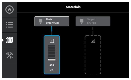
The current status of each of the material coil boxes connected to the printer can be viewed via the Materials page. To locate this information:
1.Press the Materials button within the Navigation Menu; the Materials page will be displayed.
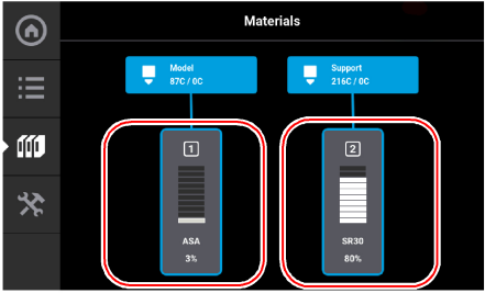
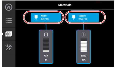
2.The Display Area of this page contains two “Material Status Icons” (page 27). The left icon pertains to the printer’s model material while the right icon pertains to the printer’s support material. The number displayed within the top of the icon indicates which material slot the material coil box is connected to (1 or 2). The colored bars (displayed within the center of the icon) and percentage (displayed at the bottom the icon) indicate the current volume of material in the box. The name of the type of material in the box is displayed at the bottom of the icon.
3.Touching one of these icons on the screen will open that material’s Material Details page (see “Viewing Material Details” (page 29)).
Figure 31: Materials Status Locations
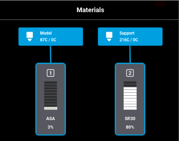
Icons and filament pathways will take on a variety of colors and highlighted states, depending on their status (see Table 7 (page 28) for detailed status explanations). Coloring pertains to both model and support Material Status Icons:
•Blue border - indicates that a valid material coil box is connected to the corresponding material slot, the blue filament pathway indicates that material from the box is loaded to the head and is selected to be used for building.
•Gray (dashed border) - an icon that is blank in the center with a gray dashed border and gray dashed filament pathway indicates that a material coil box is not connected to the printer.
•Yellow - an icon with yellow coloring indicates an issue/warning (see “Warnings and Errors” (page 1) for more information).
•A volume of 0% accompanied by solid yellow coloring indicates an empty material coil box.
•Red - an icon with red coloring indicates an error (see “Warnings and Errors” (page 1) for more information).
•A red border with a notification badge in the center of the icon indicates that the material coil box is invalid (i.e. not licensed or not compatible with the associated head type).
•A red border with a notification badge within the center of the filament pathway indicates a load related error.
•A semi-solid red icon indicates that an error occurred when checking the data on the material coil box’s memory chip and the box is unusable.
•A solid red icon indicates that communication with the material coil box is not possible.
The oven’s temperature can be viewed via the Maintenance page. To locate this information:
1.Press the Tools button within the Navigation Menu; the Tools page will be displayed.
2.Press the Maintenance button within the Tools page; the Maintenance page will be displayed.
3.Locate the Chamber row within the page. The printer’s current and set point oven chamber temperatures are displayed within this row.
Figure 32: Maintenance Page Oven Chamber Temperature

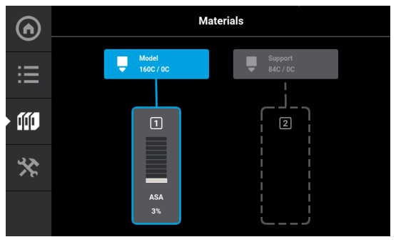
To view temperature information pertaining to the model and support heads within the Materials page:
1.Press the Materials button within the Navigation Menu; the Materials page will be displayed.
2.The Display Area of this page contains two Head Status Icons, one corresponding to the model head and the other corresponding to the support head. (See “Head Status Icons” (page 22) for details). The head’s current temperature as compared to its set point temperature is displayed within the lower portion of the icon.
3.Touching one of these icons on the screen will open that head’s Head Details page. The same temperature information is displayed within this page for both the model and support heads.
Figure 33: Materials Page Head Temperatures
Version information for the software used to control the printer (Controller Software) can be accessed via the Maintenance page:
|
|
Controller Software is installed on a flash device located on the Controller board and should not be confused with GrabCAD Print software, which is installed on the workstation PC. |
1.To access the Maintenance page, press the Maintenance button within the Tools page (see “Working with the Tools Page” (page 37)).
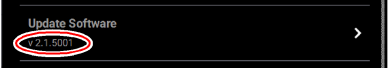
2.Locate the Update Software row within the page (see “Maintenance” (page 54)).
3.The printer’s Controller Software version information is displayed within the Update Software row.
Figure 34: Controller Software Version Information
Activating the MTConnect system enables the MTConnect data exchange protocol between the printer and an MTConnect client for the purpose of tracking printer defined metrics. MTConnect is available for all F123 Series systems and requires firmware Version 3.27.3214 or later.
|
|
Firmware version 3.31.3614 (or later) is recommended for all systems. |
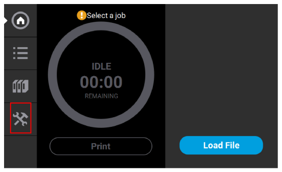
MTConnect must be enabled on the printer. To do this from the Home Screen:
1.Select the Tools screen.
Figure 35: Home Screen
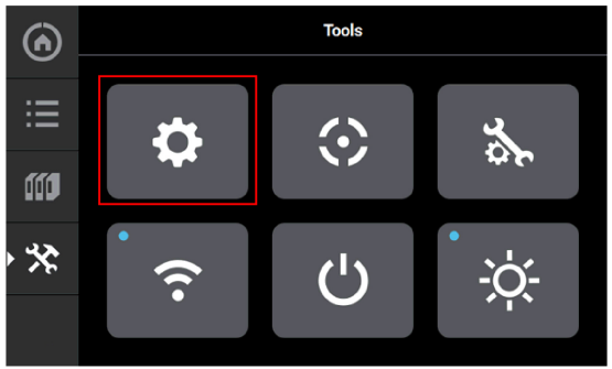
2.From the Tools screen, select the Settings screen.
Figure 36: Access Setting screen
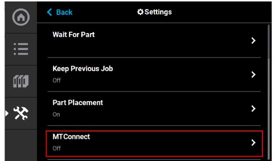
3.On the Settings screen, scroll down to tthe MTConnect setting. Select MTConnect.
Figure 37: MTConnect
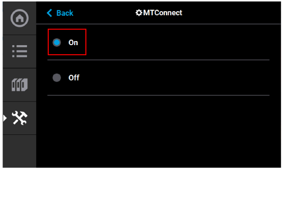
4.On the MTConnect screen, touch the On button to turn MTConnect ON.
Figure 38: Turn ON MTConnect
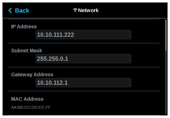
5.If the printer is connected to a network, you can you can view the device information and current MTConnect data by using a web browser as a client and the system’s IP address. The IP address can be obtained via the Network Window.
Figure 39: Network Information
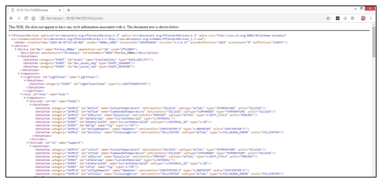
6.To verify the system is on the network, open a web browser and type http://xxx.xxx.xxx.xxx:5000/probe replacing the “xxx.xxx.xxx.xxx” with the obtained IP address. The device information is returned.
|
|
The IP address need not be in 3 digit segments. Do not use leading zeros. For Example: IP Address = 10.40.202.149, use http://10.40.202.149:5000/probe, NOT http://010.040.202.149:5000/probe |
Figure 40: Computer Information
7.Change “probe” to “current” (http://xxx.xxx.xxx.xxx:5000/current) will return the current MTConnect data for the system.
Figure 41: MTConnect Data

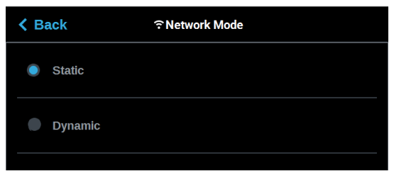
8.You can still view the device information and current MTConnect data by using a web browser as a client and the system’s IP address even if the printer is not on a network. You can do this by directly connecting a computer to the printer with a Crossover Cable connected to the Ethernet Ports. Ensure the Static radio button is selected on the Network Mode window.
Figure 42: Static Network
.
9.Connect a computer to the printer at the ethernet ports using a crossover cable.
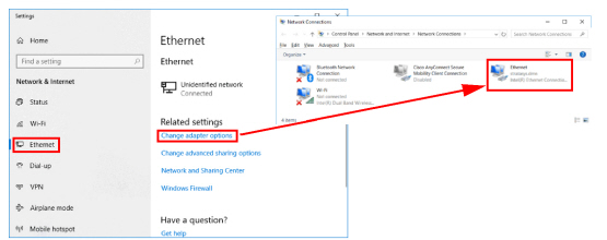
10.Navigate to the computer’s Ethernet Network Settings and select “Change Adapter Options”.
11.Right click on Ethernet and select Properties.
Figure 43: Locate Ethernet Settings
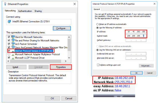
12.In the Ethernet Properties screen, using the images below as a general guide, set the “IP address” to match the printer’s, EXCEPT change the last triplet to another number between 1 and 255.
13.Set the “Subnet mask” to match the printer and click OK.
14.The computer and your printer can now communicate like an “isolated” network. The previously explained method of using a browser as a client will work.
Figure 44: Ethernet Properties