3 System Components
This chapter describes the components of the F123 Series. Information regarding the materials and tips that can be used by the printer is also included in this chapter.
|
|
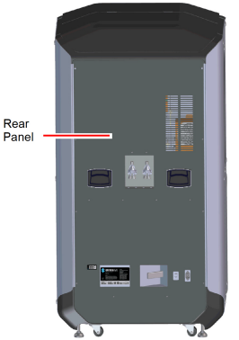
Do not energize when the rear panel is not secured in place. |

This printer has been designed to allow easy access to the most frequently accessed areas on the system. Doors and panels are highlighted in Figure 1 and Figure 2.
Figure 1: Access Doors and Panels - Front View
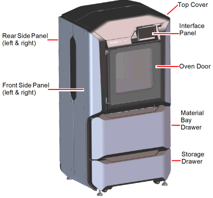
Figure 2: Access Doors and Panels - Rear View
Allows access to the gantry and head assemblies.
Allows access to the platen, tip wipe assemblies, purge area, and completed parts for removal. The printer’s camera is also housed within the oven door.
Allows access to the material bay components (material bays, material spools, and the material drive controllers).
Provides a built-in area which can be used for miscellaneous storage of spare parts, tools, etc., as needed.
The right and left side panels provide access to the oven chamber fans.
The rear panel provides access to the electronics bay.
The interface panel houses the printer’s touchscreen user interface, power button, and USB ports.
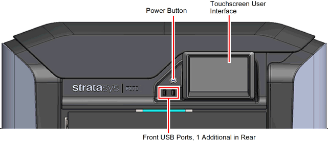
Allows for user control of the printer. From the User Interface you can access various screens to select jobs for building, control jobs in the process of being built, change materials, perform calibrations, and configure your printer’s settings and maintenance options. The touchscreen visually displays the operational state of the printer as well as any warning information available.
See Chapter , 4 User Interface (page 1) for detailed information on the components and pages of the user interface.
Allows you to power the printer ON and OFF (see “Powering ON the Printer” (page 1) and “Powering OFF the Printer” (page 2) more information).
The printer’s USB ports allow you to easily upload job files to be built. After plugging a USB flash drive into any of the USB ports you can access the flash drive’s contents via the Queue page (see “Working with the Queue Page” (page 13) for details).
The oven consists of the oven door and everything that you see through the oven door window, including the platen, tip wipe assemblies, purge chute, and oven heaters. The printer’s camera is housed within the frame of the oven door.
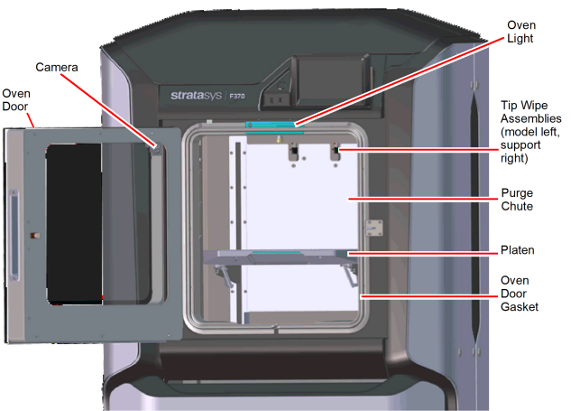
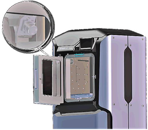
The oven door (see Figure 4) utilizes an electromagnetic lock along with optical sensors. The oven door remains locked while the printer is building and automatically unlocks when it is safe for you to access the components of the oven. You cannot open the oven door when the printer is building. The top cover will automatically unlock in conjunction with the oven door, allowing you to manually open the top cover. The oven door must be open prior to opening the top cover. The oven door gasket, which runs around the perimeter of the oven door frame, helps to provide an airtight seal when the oven door is closed.
The oven door window is composed of 2 panes of tempered glass.
The printer’s camera is housed within the frame of the oven door and provides remote monitoring capabilities while a part is building. Using the GrabCAD Print application installed on your workstation PC, you can view the part as it is building allowing you to remotely monitor part build quality. Pictures are automatically taken at a set interval via GrabCAD Print. Please note that the camera image displayed will include some reflection as a result of the oven door’s glass.
Figure 5: Camera Location
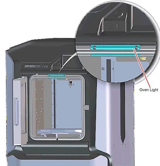
A single light pipe is mounted on the front upper edge of the oven and is used to illuminate the oven chamber (Figure 6). The light pipe consists of nine high-temperature LEDs; each LED is rated at 1-watt. The oven light is powered by 12 VDC.
The Light button within the Tools page indicates the current state of the oven light and allows you to manually turn the light ON of OFF (see “Light” (page 67)).
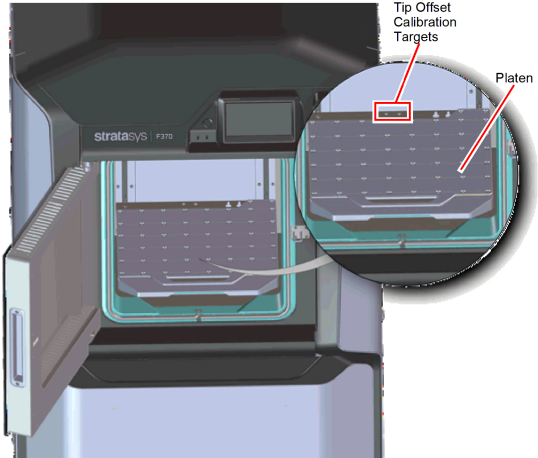
The steel platen provides the level surface on which parts are built. A substrate is securely affixed to the platen using the substrate ejection handle. After placing a substrate on the platen lifting up on the handle will lock the substrate into its build position; pressing down on the handle will release the substrate from the platen for removal.
The tip offset calibration targets are located on the rear center portion of the platen. These targets are used when determining the X and Y offset between model and support tips after either head has been replaced (during an automatic Tip Offset Calibration).
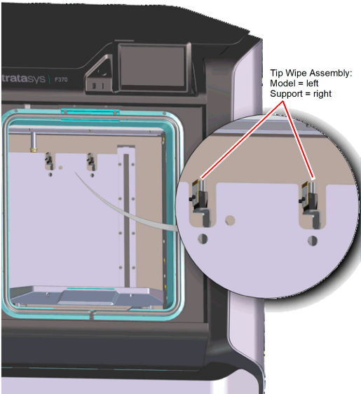
Two tip wipe assemblies are located in the rear of the oven, one for model and one for support. Each assembly consists of a flicker and a brush. The tip wipe assemblies keep the printer’s tips and tip shields free of purged material debris and material buildup.The tip wipe assemblies are mounted behind the purge chute and extend through the purge chute via two slots cut into the chute’s exterior.
After material is purged from a tip, the tip passes across the tip wipe assembly. The flicker cuts the purged material from the end of the tip and knocks it into the purge chute. The brush cleans the tip and tip shield. Purged material debris is guided down from the tip wipe assemblies to the bottom of the oven chamber via the purge chute.
Figure 8: Tip Wipe Assemblies
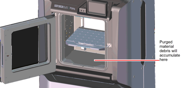
The purge chute is located in the back of the oven. Purged material debris is guided down from the tip wipe assemblies to the bottom of the oven chamber via the purge chute. Material debris exits the purge chute via an opening at the bottom of the chute and then accumulates in the bottom of the oven chamber. Accumulated material debris should always be cleaned on a weekly basis, or as needed if excessive accumulation occurs, see “Cleaning the Oven Chamber” (page 12) for instructions.
Figure 9: Purge Chute Location
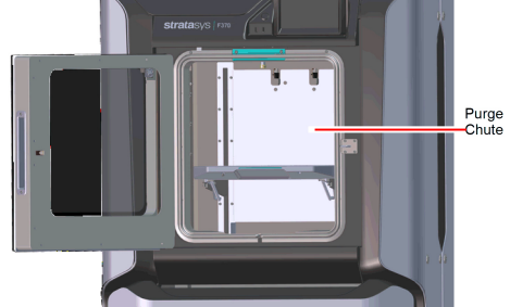
Figure 10: Oven Chamber Cleaning Location
Material Bay Drawer Components
The model and support material bays are accessible by opening the material bay drawer on the front of the printer. The material bay drawer does not contain any locking mechanisms and can be opened while the printer is building.
Figure 11: Material Bay Drawer Components
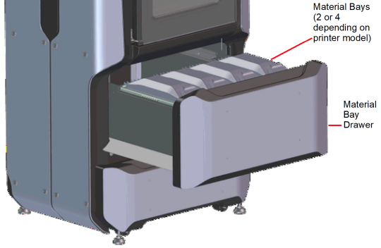
The F270 and F370 printers have four operating material bays - two model and two support. The two left-most bays hold model material while the two right-most bays hold support material. The F170 printer has two operating material bays - one model and one support. The left bay holds model material while the right bay holds support material.
While building, one model and one support spool will be active. An active spool has material filament loaded to the head, as indicated by a solid blue pathway between the Material Status Icon and corresponding Head Status Icon, a solid blue Head Status Icon, and a solid blue border around the Material Status Icon on the touchscreen display (see “Materials Status” (page 29) for more information). For applicable printer models, you can replace inactive spools without pausing the printer.
|
|
The auto changeover capability automatically loads a second spool during a build when the first spool runs out of material (see “Material Auto Changeover” (page 10)). Auto changeover is only applicable for the F270 and F370 printers. |

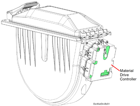
Each individual material bay has a material drive controller. The material drive controller feeds filament from a material bay to the head. The material drive controller is located on the back side of the material bay and contains a small 12 VDC motor which drives filament up to the head. The material drive controller is a non-serviceable item and is instead replaced along with the replacement of a material bay.
The material drive controller contains a mechanical filament present switch which detects the presence of material within the material drive during the load and unload process. This switch also detects errors. If the material drive controller detects that filament has broken within the material bay or the end of filament is reached, the printer will pause to allow for recovery.
Figure 12: Material Drive Details
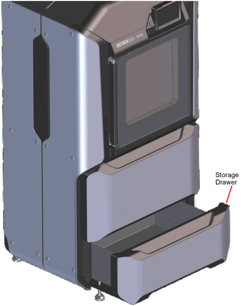
Directly below the material bay drawer is a storage drawer which can be used to store spare parts or tools, as needed.
Figure 13: Storage Drawer
To access the gantry or the heads, you must first open the top cover. The top cover utilizes a mechanical locking mechanism. The top cover remains locked while the printer is building and automatically unlocks when the oven door is opened. The printer cannot resume building if the top cover and/or oven door are open.
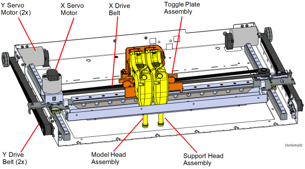
The gantry moves the head in the X and Y directions when building a part. The gantry assembly is located under the top cover. The entire gantry is outside of the oven; only the bottom of the head protrudes into the oven. The gantry and its drive motors are thermally shielded from the oven via flexible heat shields. To move the head, the gantry utilizes one X and two Y servo motors attached to timing belts.
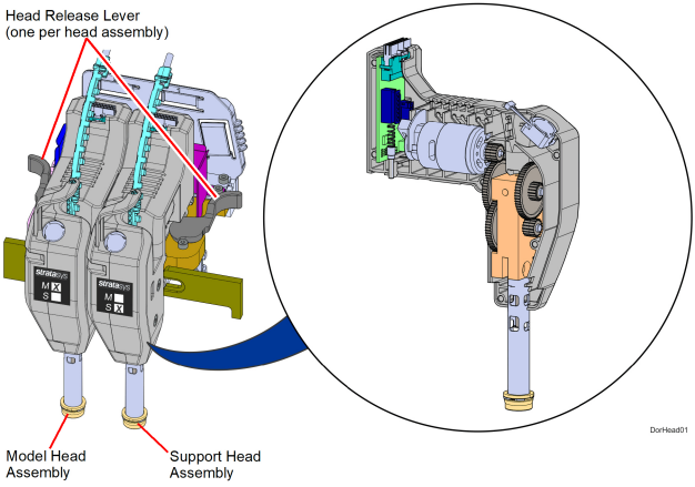
The F123 printer utilizes five print head assemblies, one for standard model and support material, one for TPU 92A (Elastomer), one for ABS-CF10 model material, one for PLA model material, and one for the PLA cooling module. The standard model and support heads are black. The TPU 92A model head is blue. The PLA head is dark gray. Once a head has been used for standard model or support, it can only be used for that designated material (model or support) thereafter. The TPU 92A head can only be used for TPU 92A material. The ABS-CF10 head is green and can only be used with ABS-CF10 material. The standard model material head can be used with ABS-CF10 material (even after standard materials have been used), but head life will be negatively impacted due to the carbon filled material. The standard head can be used exclusively with ABS-CF10 material, but the head life will be 700 hours. Also, the head life warranty for the standard head is not guaranteed if a mix of standard material and ABS-CF10 material is used. While standard material may be used after ABS-CF10, it is not recommended for Diran which will exhibit poor part quality. The PLA head can only be used for PLA material. The heads are designed for use with a range of modeling materials. The heads extrude model material and support material with two identical liquefiers. A single blower fan, mounted above the tip liquefier entrances, cools the incoming material at the liquefier entrances.
Head life is directly related to the amount of build time for the head. Heads are a replaceable consumable item and should be changed once the head’s odometer reaches 1500 build hours (see “Viewing Head Details” (page 24) for information on head odometers). You will receive a warning when the head’s odometer reaches 1350 build hours, reminding you to order a replacement head as the head is nearing its odometer limit. The standard head life will diminish if ABS-CF10 material is used. Head life for both a standard head and the dedicated ABS-CF10 head is limited to 700 hours. The warning for the ABS-CF10 head occurs at 600 hours. You can continue using a head which has exceeded its odometer limit, but it is highly recommended that you change the head as part quality will be unpredictable. The corresponding Head Status Icon will be displayed in its warning state on the User Interface (seeTable 6 (page 22) for icon states). The entire model or support head assembly is replaced as a single unit (see “Head Replacement” (page 12) for instructions). The Head Release Lever locks and unlocks the associated head into or out of its seated position.
When building with PLA material, a specialized PLA head is used. The PLA head must be installed into the model head location within the gantry. A cooling module is used in conjunction with the PLA model head and must be installed into the support head location within the gantry (seeTable 4 (page 4) for help identifying the cooling module). When building with PLA material, the PLA model head extrudes both model and support materials. (See “Replacing a PLA Head” (page 14) for instructions on replacing a PLA head or the associated cooling module).
Table 1: Print Head
|
Head Type |
Head Color |
Model Materials |
Support Materials |
|---|---|---|---|
|
Standard |
Black |
ABS, ABS-CF10, ASA, PLA, PC-ABS, TPU 92A, |
QSR, SUP4000B1 |
|
TPU (Elastomer) |
Blue |
TPU 92A |
|
|
ABS-CF10 |
Green |
ABS-CF10 |
|
|
PLA |
Light Grey |
PLA |
Natural, Red, Yellow, Green, Blue |
|
PLA Cooling Module |
Light Grey |
|
Air cooling only |
|
1 Used with Diran™ 410MF07 only. |
|||
The F123 Series can use a variety of model materials, in a range of colors. QSR Soluble Release support material is used in conjunction with all model materials, except for PLA. When building with PLA material, PLA is used for both model and support materials (see Table 4 (page 18) for model and support compatibility information).
Table 2 (page 16) lists the material types available for use with each printer model.
Table 3 (page 16) lists color availability by model material type.
Each material spool has an axle with a memory chip; this memory chip recognizes the spool’s material type and tracks the spool’s volume. The F123 Series utilizes a different memory chip than other Stratasys materials and as a result, only F123 Series compatible spools can be used to build parts on the printer.
Figure 16: Material Spool Memory Chip Location
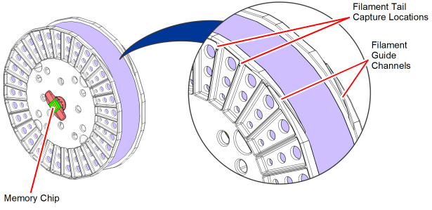
When a spool is installed, its memory chip is read and the spool’s information is reported to the printer. The spool’s material type and volume are displayed within the Materials page of the User Interface (see “Working with the Materials Page” (page 21) for more information). If a non-compatible spool is installed an error will be displayed on the User Interface.
Each build file contains an estimate of the amount of model and support material required to complete the build. When initiating a build, this estimate is compared to the amount of material available on each spool. If there is not enough material available to complete the build, you will be warned and given the option to change spools or install additional spools before starting the build.
|
|
A specific prompt will only be displayed if a spool volume related issue is detected. See “Warnings and Errors” (page 1) for details. |
Tips, Slice Height, and Build Sheets
The F123 Series utilizes a T14 tip for all model and support materials. Tips are a component of the associated head assembly and cannot be changed individually. Instead, the entire head assembly is replaced as a single unit.
Table 4 lists the types of model material available for use with the printer, their corresponding support material, and their corresponding build sheets.
Table 5 lists available slice heights.
|
Model Tip |
Slice Height (in) |
Slice Height (mm) |
Material |
|---|---|---|---|
|
T14 |
0.005 |
0.127 |
ABS, ASA, PC-ABS |
|
0.007 |
0.178 |
ABS, ASA, PC-ABS, |
|
|
0.010 |
0.254 |
ABS, ASA, PC-ABS, PLAa, TPU 92A, Diran™ 410MF07, ABS-CF10, ABS-ESD7™ |
|
|
0.013 |
0.330 |
ABS, ASA, PC-ABS, |
|
aAvailable in “Draft” mode only |
Controller Software is installed during the manufacturing process, and can be updated as new versions become available (see “Updating Controller Software” (page 1) for instructions). Controller Software is the software used to control the printer.
The printer builds parts by processing an original CAD or STL file into a Stratasys CMB file which is then downloaded to the printer. GrabCAD Print is the software used to process files and then transfer them to the printer to be built. As part of the initial installation and setup process, you must download and install GrabCAD Print software. You must download this software before you will be able to build a part on the printer. To download GrabCAD Print navigate to http://help.grabcad.com/article/197-sign-up-download-and-install and follow the on-screen steps.
Jobs are sent to the printer in CMB format and placed into the Job Queue (see “Working with the Queue Page” (page 13) for information on the Job Queue.) The header of the CMB file contains the processed job’s basic information.
The GrabCAD Print Help documentation includes detailed information on how to connect to your printer, process parts, edit the Job Queue, etc. The Help file can be accessed from either the application’s Help Menu or directly from the GrabCAD website.
Insight is a software application used for processing STL files. Insight provides the user with the ability to utilize advanced features and manipulate numerous parameters within the file. For most applications, GrabCAD Print software will provide sufficient capabilities. However, in some cases, the advanced capabilities of Insight may be required.
When using Insight with the F123 Series, use the following process:
1.Open and process the STL file.
|
|
Insight will only process STL files. |
2.When completed, save the CMB file to a known location.
3.In GrabCAD Print, navigate to File > Import File and select the CMB file you wish to import.
4.Continue with normal work flow using GrabCAD Print.