About this Guide
As with other manufacturing techniques, the 3D printing process can be challenging and demands a level of expertise and familiarization.
This guide aims to help designers produce quality and cost-effective parts on Stratasys PolyJet 3D systems. The guide provides information for both new and experienced users.
The topics covered in this guide describe tools and methods for optimizing design features, strength, and durability of printed parts, and ensuring that the parts meet your expectations. It provides best practices and tips on designing for additive manufacturing, and examples of how to take advantage of Stratasys unique features to get the most out of your PolyJet printer, while minimizing printing costs and post-processing issues.
If you have any questions or comments about the way information is presented in this guide, or if you have any suggestions for future editions, please send a message to c-support@stratasys.com.
Visit the Stratasys Support Center to download the latest revision of this document. This document is also available there in other languages.
Stratasys encourages you to learn more about your printer and its capabilities in real-world settings. A wealth of information is available at the Support Center, your portal to thousands of knowledge assets, including information on design, applications, materials and Web-based training. The site also has links to "how-to" videos and the Stratasys blog.
Another source of 3D printing tips is the Tutorials section of GrabCAD Community.
PolyJet 3D printing technology uses photopolymers that are jetted onto a build tray in very small droplets and immediately cured with ultraviolet light to build a 3D printed part.
Figure 1: PolyJet technology
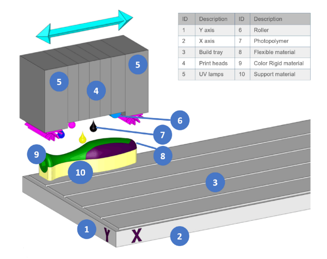
Stratasys PolyJet 3D printers use this technology to create parts that incorporate complex shapes, intricate details, delicate features and a high-level realism. PolyJet 3D printers can print the widest variety of multiple material and color combinations at once and at a higher resolution than other 3D printing technologies, such as FDM. These printers, can blend two to six or seven model materials to obtain an array of features like soft touch over-molding, a full range of color, and even clear and transparent gradients in a single printed part. All this makes PolyJet technology very attractive for multiple industries when creating realistic prototypes and tactile end-use-parts.
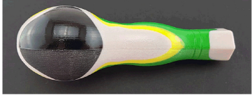
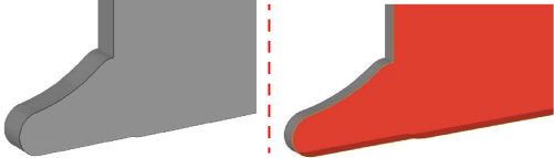
One of the major benefits of the PolyJet 3D printing system is the support material that is printed simultaneously with the modeling material and facilitates fast print speeds. By default, the support material is only placed where it is needed, on downward facing surfaces, to support parts while they are printing. For those familiar with the considerations required when printing in FDM, in PolyJet there is no self-supporting angle; any overhanging geometry will require support. Areas of a model that face upward will have a high gloss surface finish and areas that face downward, which have been in contact with the support material will have a matte surface finish.
Figure 2: Screwdriver handle prototype with a glossy finish areas and a matte finish areas
A uniform matte finish can be achieved by selecting the matte surface finish in the pre-print preparation software. This automatically adds a coating of the support material around the printed part resulting in a tactile matte finish. The support material is easy to remove manually, by hand or waterjet, and or in a chemical solution bath. A few quick and simple post processing steps can be employed to achieve parts that have a uniform high gloss finish.
Below is a short overview of some of the most common PolyJet printing materials and their combinations.
Getting to Know the PolyJet Materials
PolyJet printing materials can be printed as single, base material, or they can be mixed to create composite materials, or digital materials.
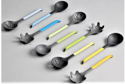
Figure 3: Models incorporating PANTONE colors enabling a full range of styles to be explored
Flexible Materials: (Agilus/Tango Family)
The PolyJet flexible materials can be used to mimic rubber or to add soft-touch finishes to parts. The Agilus materials are ideal for advanced design verification and rapid prototyping, as well as applications, such as wearables, jigs and fixtures and many others.
Prototyping Rigid Materials (Vero/VeroVivid Family)
This is a rigid family of materials that can be printed as a single material or in combination with other materials. These materials can be used for a variety of applications, from form-fit visual models, including functional part, such as tooling, jigs & fixtures, and sheet metal forming matrices. They are well-known for being used to create smooth, strong parts and prototypes that closely simulate the final product. The Vero family is extensive, incorporating basic white, black and gray materials along with cyan, magenta and yellow materials available in both opaque and transparent variants that can be combined to create over 500,000 unique colors. This enables full color models that can be further enhanced with the addition of a glass clear material to enable advanced designs impossible in any other technology.
Designers and engineers can apply these colors and transparencies to their part from within their design software or through GrabCAD Print our dedicated pre-print preparation software. This ability dramatically cuts post-processing and painting time. PANTONE-validated color options in these printers make communication from design to part simpler, and color consistency more accurate and easier than ever to achieve.
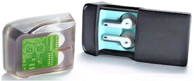
Figure 4: Clear material used as a visual aid to show internal components
Rigid and Flexible Combinations (Agilus and Vero Family)
One of the most common digital materials is a mixture of our rigid and flexible materials. By mixing these two materials, you can control the level of hardness or softness in different areas of the part you are printing. This makes combinations ideal for simulating buttons or over-molding. You can also combine rigid color material with the flexible Agilus materials, but, with these combinations it may not be possible to achieve both the accurate color and a specific shore value. In general, the more color you add, the more rigid your part.
Advanced Materials (Digital ABS Plus, Rigur, High Temperature)
In addition to these standard prototyping materials we have a range of advanced materials with enhanced properties.
Figure 5: Digital ABS Plus hand drill prototype with wood color handles printed on the J750
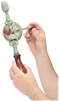
Digital ABS Plus suitable for advanced prototyping applications provides great strength, durability and heat resistance, as well as a great surface finish. It uses two materials, one high strength and one with high heat resistance. When these materials are printed together, you can achieve a part with similar mechanical properties to ABS. This is ideal for prototyping injection molding tools, where surface finish is a priority. Digital ABS Plus can also be used in a range of applications that require enhanced mechanical properties or that will be subjected to more robust handling, wear and tear. Examples of additional applications include hinges or snap fits, where strength and durability are needed.
Other advanced materials include:
•Rigur—Polypropylene type material that is perfect for snap fit components and modes that require durability when subjected to dynamic loads
•High-Temperature—a material that is suitable for high temperature applications
•Medical/Dental—materials for medical and dental applications with appropriate biocompatibility certifications.
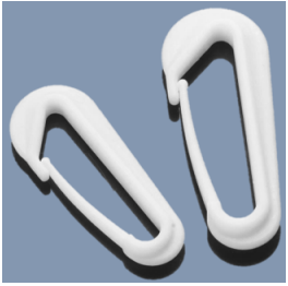
Figure 6: Polypropylene-type clip printed with Rigur
General guidelines:
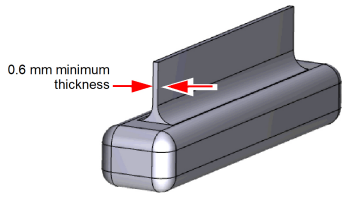
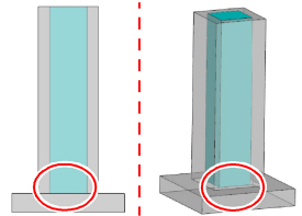
•Designed parts should have a minimum wall thickness of 0.6 mm.
•Very tall, thin walls are prone to breaking. Walls above 30 mm should be printed with a matte finish rather than a glossy one.
•Prefer the Wide support policy setting for tall, thin parts.
Figure 7: Minimal wall thickness
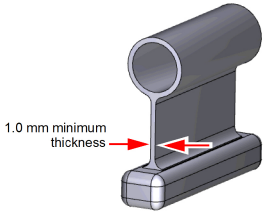
•If the wall is load bearing or part of a structure, the wall thickness should not be less than
1 mm.
Figure 8: Minimal wall thickness for load bearing
|
|
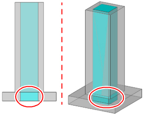
Large, thin walled sections and features may be difficult to post process, because they are typically very fragile. |

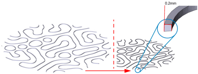
Using PolyJet technology, you can print highly accurate feature details.
•Details of 0.2 mm are visible and crisply formed.
Figure 9: Tolerance for fine details
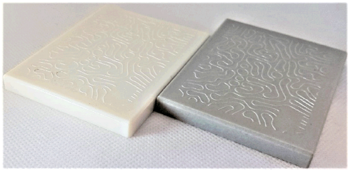
•The printing material or color selection affects the visibility of the fine features.
In the figure below, the pattern details are more visible on the VeroGray print part.
Figure 10: Pattern with fine details printed using different materials
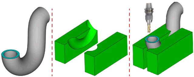
•If high tolerances are required:
•For holes, the parts should be modeled undersized
•For mating surfaces, the parts should be modeled oversized
Then, the parts can be machined to final size.
Figure 11: Material added to mating surfaces (left); hole with smaller diameter to be tapped after printing (right)
|
|
During machining operations, use slow cutting and feed speeds to ensure minimum force is applied to the cutting tool and printed surface. |
|
|
Pro Tip: You can design and print jigs that conform to the part geometry, and use them to secure and orient the part correctly for subsequent machining. |
Figure 12: Original part (left); fixture (center); part in fixture (right)
The pre-print preparation software (such GrabCAD Print) assess the model to determine which surfaces of the model are internal and which are external. When encountering internal overlapping regions, the software may add support material in areas where there are voids or spaces. GrabCAD Print features a smart boolean capability that resolves material assignments in certain situations, for example it eliminates the need to perform boolean operations when you have a small body within a larger one.
Figure 13: Small bodies inside a larger one
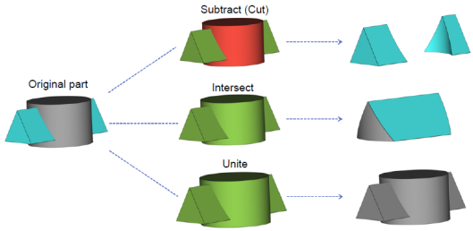
Typical Boolean operations that can be performed on the model elements to create single bodies or defined separate bodies are described below.
•Boolean Subtract (Boolean Cut)
This operation subtracts one part from another. The user specifies which part to subtract from the other. In the image below, the main body is green and the part to subtract is red.
•Boolean Intersect
This operation creates a new body of the area, where several parts overlap.
•Boolean Unite / Merge
This operation merges the selected files into one file and trims all the surfaces to make one shell of both parts. There is no limit on the number of files that can be united.
Figure 14: Boolean subtract, intersect, and unite operations
Single Material Selection of Overlapping Geometry
The example below shows a model that contains two overlapping shells. As designed, the model is printed using a single model material. However, the interface between the two shells may be filled with support material. By performing Boolean operations, you can easily adjust the model to ensure that there is no overlapping area.
Figure 15: Original geometry
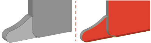
Figure 16: Geometry after Boolean merge operation
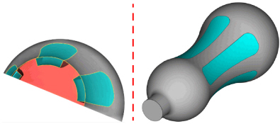
Multi-Material Selection of Overlapping Geometry
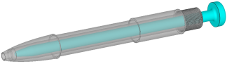
The example below shows an overlapping issue when adding flexible inserts to a screwdriver handle for better grip. As designed, the flexible inserts overlap with the rigid material in the handle. This can cause incorrect color or material assignment in the overlapping area.
Figure 17: Part as designed (left); overlapping between handle and grip (center and right)
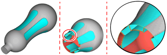
By performing Boolean operations, you can easily adjust the model to ensure that there is no overlapping.
Figure 18: Part after Boolean Cut operation
Designing Assemblies for All-in-One Print
With PolyJet, it is possible to print moving part assemblies, pre-assembled on the build tray.
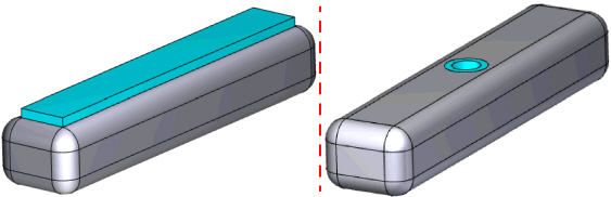
Tolerances
•For all-in-one prints of assemblies, leave 0.2 mm clearance between parts.
Figure 19: Gaps for all-in-one print assemblies
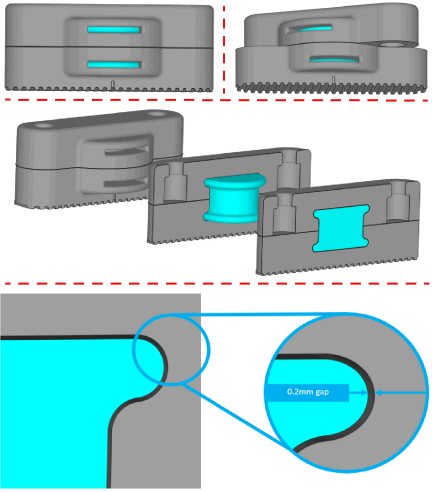
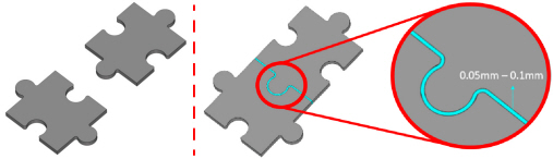
•For fitting parts printed separately that are assembled after printing, leave between 0.05 to 0.1 mm between parts.
Figure 20: Parts printed separately and intended to be assembled after printing
|
|
When designing moving areas from which support may be difficult to remove or extract, it is recommended to create slots or openings to help remove support material, as shown in Figure 52 (page 31). |
Removing support material from small voids and enclosed sections of the model can be difficult.
Figure 21: Enclosed hollow
•Designing deep voids (over 50 mm) with exit holes, can speed up post processing and final part finish. This is especially important for movable sections and clear parts.
The figures below show examples for possible solutions that can be applied when designing the model.
|
|
The solutions depends on the final application, aesthetics, and functionality of the part. |
Figure 22: Solution 1—An opening at non-critical area in the model
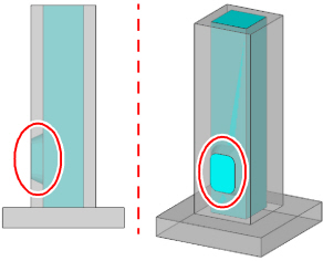
Figure 23: Solution 2—An opening at one of the ends of the model
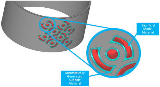
•Additionally, for long, enclosed sections that are filled with support material the removal time can be drastically reduced by designing a sacrificial part that can be removed after printing and provides an entry point for the water jet or caustic soda solution.
Figure 24: Long enclosed section, difficult support removal
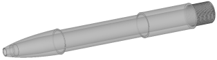
Figure 25: Long enclosed section with sacrificial part for easier support removal
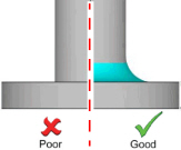
Adding Fillets for Increased Strength
Adding fillets, where two different sections of the geometry meet, provides additional reinforcement and stress relief.
Figure 26: Model with and without fillets
•Placing a larger fillet radius on internal surfaces, increases strength and decreases the effect of thin walled sections with fillets acting as a spring.
Figure 27: Large fillet radius for sections acting as a spring
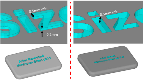
For embossed and engraved details follow these recommendations:
•A minimum line thickness of 0.5 mm
•A depth of 0.5 mm is optimum
•A raised height of 0.2 mm above the surface of the model
•Font selection is important. A bold sans serif font, such as Arial bold / rounded is ideal.
Figure 28: Recommendations for text creation
|
|
•When creating text on parts, it is a recommended to make sure that you save the text STL files as a single shell. This can easily be done using software, such as Materialise Magics. Saving the text as one STL file, makes it much faster to select the material for the text in GrabCAD Print. This enables you to select one shell versus multiple shells for each letter. •When applying text as an image texture (VRML/OBJ), only the font size needs to be considered. |
Sacrificial Geometry for Build Support in Thin Wall Structures
Tall and thin walls with detailed features that have gaps between the features cause thin walls of support material to be added. These thin support walls may not provide enough structure for the upper model material, resulting in an incorrectly printed part. Additionally, for fragile filigree-like elements, the printed model may become damaged during support material removal.
The solution to this problem is to fill in the spaces between these features with a sacrificial offset (0.4 mm) wall of model material. This provides more structure than a wall made of support material and is easily removed during post processing with less chance of damaging the detailed features.
Figure 29: Part designed with filigree elements
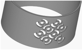
Figure 30: Part design adjusted to protect the delicate features
Follow these recommendations and considerations to print screws and threads.
•When printing very small threads that will be subjected to regular operation, the threaded section may become stripped over time. Off-the-shelf hardware will be more durable.
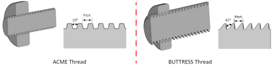
•When printing threads:
•It is not recommended to print threads below M5. Although they are printable, they are unlikely to hold up to any torque without the thread stripping.
•An ACME or BUTTRESS type screw-thread should be used. For best results, ensure an offset clearance between mating parts of 0.15–0.2 between the male and female threaded section.
Figure 31: ACME thread (left); BUTTRESS thread (right)
|
|
Prefer a matte surface finish when printing threads to avoid binding while in use. |
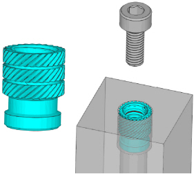
Screws, Bolts, and Threaded Inserts
Follow these recommendations and considerations to incorporate off-the-shelf hardware into a printed part.
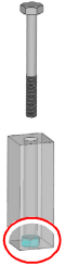
•For screws that will be subjected to regular use, print a socket or a pocket for the nut (with a 0.1 mm offset) that can be press fitted into position. If the screw or bolt will be subjected to frequent extraction and re-insertion, then glue it in place.
Figure 32: Printed cylinder
•Design a cylinder, which will be manually tapped after printing, or design a rough thread to be printed, and then, manually tapped to clean up the channel.
Figure 33: Manually threading a printed cylinder
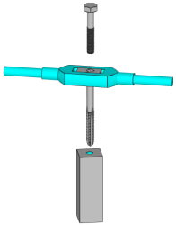
|
|
Take special care when tapping threads to regularly reverse the direction of the cut to clear chips and debris, and it is recommended to use cutting fluid or a lubricant. |
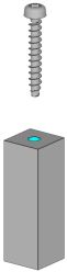
•Avoid using self-tapping screws (for plastic) for applications that require frequent assembly or disassembly, as the threads may shear and the bosses may crack.
Figure 34: Self-tapping plastic screw
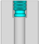
•Use press fit or heat-set threaded inserts.
•When designing for heat-set inserts, design extra space/tolerance around the diameter of the insert so that the adhesive can bond effectively.
Figure 35: Offset for adhesive
|
|
PolyJet plastics are thermoset, rather than thermoplastics, and do not melt. As a result, heat-set inserts should be affixed with adhesive glue and not fitted with heat. |
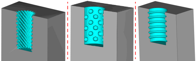
•The knurled textured outer surface on heat-set inserts make them very effective for providing plenty of surface area for adhesive.
Figure 36: Heat set insert (left); heat set insert glued (right)
•Use either a 2-part epoxy or Cyanoacrylate (CA) glue.
•Make sure that adhesive is not applied on the internal thread.
•Make sure that the adhesive has fully cured before inserting screw.
|
|
Follow the manufacturer’s instructions for curing duration to ensure that the adhesive is fully cured. |
•Add textured geometry to the inside of the insert housing to provide greater surface for the adhesive.
Figure 37: Types of textured geometry that aid adhesion
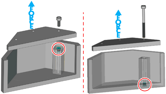
•If possible, design the insert so that it is inserted from the underside of the part and the bolt pulls against the shoulder of the pocket for extra strength.
Figure 38: High probability of fixture failure (left); strong resistance to pull force (right)
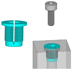
•Use an expanding threaded insert.
Figure 39: Expanding threaded insert (left); expanding threaded in place (right)
|
|
Create larger bosses around the threaded inserts to provide extra support for the insert. |
Snap-fit tabs are used in many applications, from enclosures to clasps, and are used in product assembly to make the use of screws and additional processes redundant.
Figure 40: Snap-fit applications
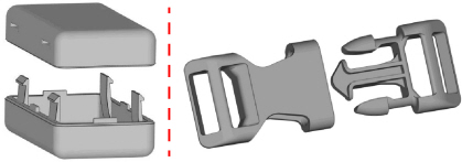
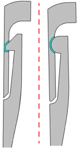
•Snap fits can be designed to be locking and inseparable, or in a way that enables frequent operation with a secure fit in the engaged position.
Figure 41: Snap fit designs—inseparable (left); separable (right)
•A simple cantilever style snap fit is the most effective.
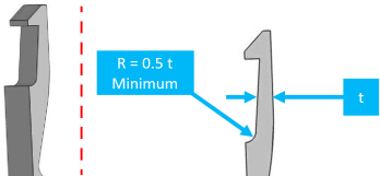
•Long snap-fit tabs should be slightly tapered towards the tip for an even distribution of stress.
•For longevity, the tab should be created with fillets at the base.
•The fillet radius should be at least 0.5 the thickness of the cantilever.
Figure 42: Snap-fit tab (left); correct design (right)
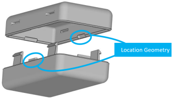
•To remove some of the shear stresses from the snap fit, add location geometry guides to other parts of the model.
Figure 43: Location geometry on an enclosure
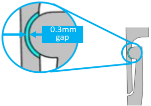
•A tolerance/clearance of 0.3 mm between parts is recommended.
Figure 44: Clearance of 0.3 mm
Other types of snaps that are easily printable can be used, including snap pins.
Figure 45: Snap pin disassembled (left); snap pin assembled (right)
•Design snap pins with the same considerations as snap-fit tabs.
•For firmer, more positive snaps, the taper can be removed.
Figure 46: Firmer snap-difficult to operate (left); snap with taper-for frequent operation (right)
Ball joints are commonly used in the toy industry and have many other applications.
You can print two types of ball joints:
•As one part in an assembly
•As two separate parts that snap together after printing
Figure 47: Ball joint printed as an assembly (left); ball joint printed as separated parts (right)
•Tolerances for ball joints can be especially challenging as too tight of a fit does not allow the ball to enter the socket, and too loose of a fit allows the ball to fall out easily. Some iterations may be required for different sized joints to reach the optimum operation.
•A joint that is opened and closed frequently rather than rotated as a pivot, wears our more easily and may no longer function effectively after repeated use.
Print-in-Place (Assembly) Ball Joints
These type of joints are printed with the ball and socket as one piece and, if done correctly, are fully functional after minor support removal.
If possible include an access (support removal) hole at the rear of the socket.
Tolerances for this type of joint can be more challenging, since if the walls of the ball and socket are too close, they will fuse together and make the joint useless.
Figure 48: Ball joint printed as an assembly (left); socket opening and ball size (right)
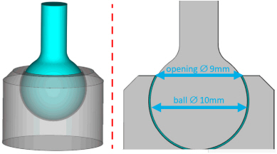
•The diameter of the socket opening must be smaller than the diameter of the ball.
For example, the socket opening is 9 mm across and the diameter of the ball is 10 mm. This joint is robust; however, it may not operate smoothly, due to leftover support.
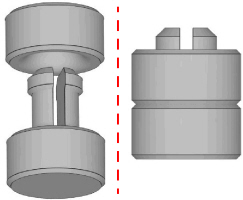
Snap-Fit Ball Joints
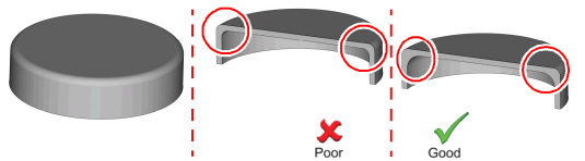
Snap-fit ball joints are a good option for creating a tight fit, which can result in posable models. This method is suitable for sectioning larger models that may otherwise require a large amount of support generation.
A ‘c’ shaped socket should be created to allow the socket to expand as the ball is inserted without breaking it. Digital ABS Plus or Rigur are good material options for this type of socket.
Figure 49: Snap fit ball joint printed separately (left); required gap (right)
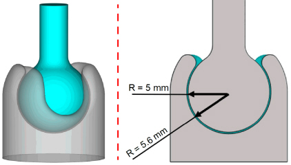
The dimensions indicated are to be used as starting point guidelines. Final design dimensions depend on ball size, socket wall thickness, printed material and printing orientation.
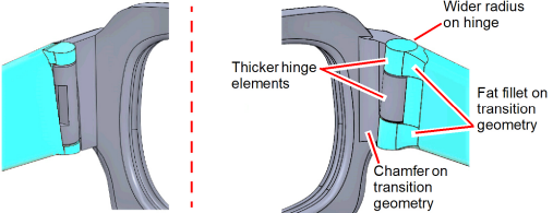
The design of the eyeglasses frame below is an example of a print-in-place hinge design. The design on the left shows the original design, and the one on the right shows a design that has been optimized for PolyJet.
Figure 50: Standard hinge (left); design corrections for printing (right)
|
|
Make sure that there is enough material to support the printed hinges and ensure durability. |
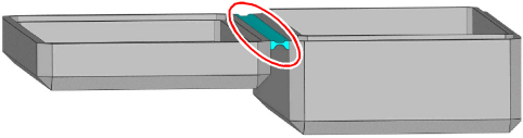
Figure 51: Hinge to be printed as an assembly
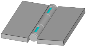
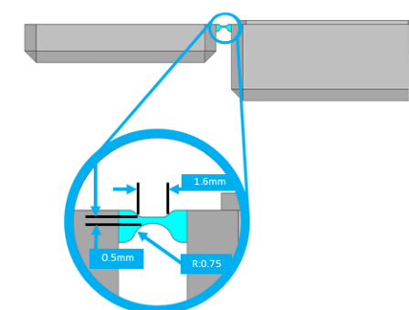
Figure 52: Design corrections for printing
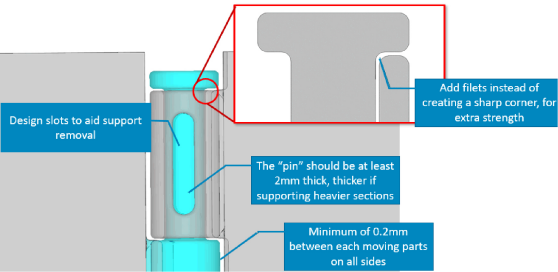
Design considerations for hinges printed with PolyJet
•Prefer a matte surface finish for the moving parts, such as hinges, so that they do not bind.
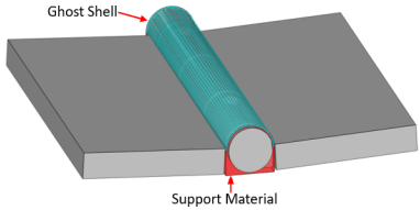
•If you need a glossy finish on the remainder of the part, design a ‘ghost’ shell over the hinge. In this way, the part (‘ghost’) is printed with a glossy finish and the elements under the ghost shell are filled with support material, and therefore, a matte finish. This ‘ghost’ shell is very thin and can be easily removed after printing. More applications and uses of ghost shells are discussed later.
Figure 53: Ghost shell added over hinge
When designing ghost shells, follow these recommendations:
•Thickness of body should be 0.1 mm.
•For a matte surface finish, the distance from parts needs to be 0.5 mm.
A living hinge is technique that is used for injection molded parts, where a thin, flexible sliver of plastic typically connects two rigid sections. The rigid sections and the living hinge are formed from one piece of plastic, and with PolyJet they can be made of different materials. The low cost and simplicity of living hinges make them a popular option for many applications.
Injection-molded living hinges can last for thousands of cycles without breaking. PolyJet
3D printed living hinges are less durable and should be primarily used for design verification, where aesthetics is critical and a low number of functional cycles are required.
•When the hinge is closed the outer edge is stretched and the inner edge is compressed. To enable this functionality, the living hinge should be designed with a longer outer surface and a shorter inner section, as shown in the image below.
•It is recommended to start the print with a hinge thickness of 0.5 mm.
Figure 55: Living hinge recommended dimensions
•For best results, the part of the hinge that is stretched should be printed facing upwards and with a glossy surface finish.
Figure 56: Orientation for a living hinge-part of hinge to be elongated printed facing up glossy
|
|
For the hinge, try selecting a shore scale between 40 -70. |
Living Hinges Designed with Agilus30
One of the strengths of the PolyJet systems is the ability to incorporate multi-materials in a single print. This feature is useful to create a living hinge that combines multi-material functionality. For example, print the body with the rigid model material, such as VeroWhite, and print the hinge with a flexible model material, such as Agilus30 White.
To take advantage of this multi-material capability, when designing the part, save each element as a separate body. In the example box shown in Figure 55 above, there are three elements: the rigid lid, the rigid box, and the flexible hinge. Defining this model as three distinct bodies allows you to assign different materials for the relevant sections. The material assignments are made in the GrabCAD Print preparation software.
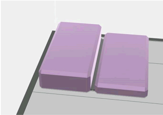
Section Parts Larger than Build Volume
Sectioning parts is a useful technique for printing parts that are larger than the printer’s build volume and for parts that require extended print times. The parts can be recombined during post processing.
There are many types of section types that can be assigned, from a straight cut to complex interlocking geometry.
Some CAD packages have tools that allow you to section a model automatically and even insert location features, like dowels or other geometries. This can also be achieved manually. These features improve the strength of the finished part and help with correct alignment during assembly of the sections.
When creating and orientating interlocking joints, consider the following:
Friction—How tight should the joint be?
•Will it be assembled with force?
•Do you need to leave room for adhesive?
•Will it be designed with a friction fit to hold parts together without adhesive?
•How will the finished part be used and in what orientation will it be printed to ensure that the loads it is subjected to do not result in part failure?
Tension—The force that will act to pull the joint apart
Shear—The force perpendicular to the joint that will try to tear the joint’s interconnecting features
Load—What forces or loads will be applied to the part?
•Will a straight cut be sufficient?
•Should teeth be used to add strength?
•How should the part be orientated during printing to reduce the risk of failure?
Below are some examples of how to section models for different loading conditions.
Figure 57: Directional forces or loads
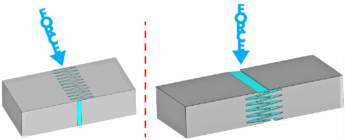
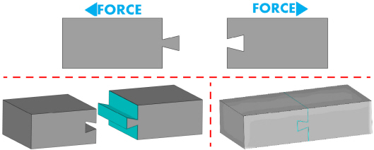
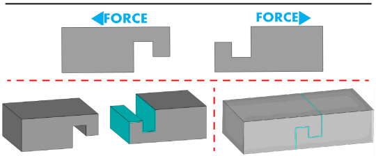
When a part needs to withstand tension consider using locking geometry features.
Figure 58: Examples of interlocking geometries
Sectioning Parts for Surface Quality
Another aspect to consider at the design phase is how the part should be designed for surface finish. With PolyJet technology, two surface finish types are available:
Matte
With a matte surface finish, the model will be covered entirely with the support material leaving a smooth matte/frosted finish.
Glossy
Any upward facing surfaces of a model will be printed with a smooth glossy finish. Undercuts and features that are not visible from directly above will be printed with a matte surface finish.
Figure 59: Part for print
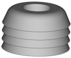
Figure 60: Part orientation on the build tray
I
In the figure below, the gray areas represent the model material and the blue areas represent the support structure. Areas that are in contact with the support material will be printed with a matte finish.
Figure 61: Glossy finish on top (left); matte finish on top (right)
|
|
For a more in-depth explanation on this topic, read to our GrabCAD tutorial on a matte and glossy surface finish. |
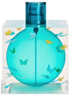
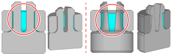
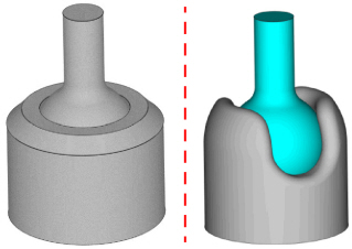
Let us examine the following example of nail polish bottle model.
Figure 62: Printed nail polish bottle
When printed as a single part, support material is printed under the overhanging sections, resulting in a matte surface finish.
Figure 63: Nail polish bottle designed as single part
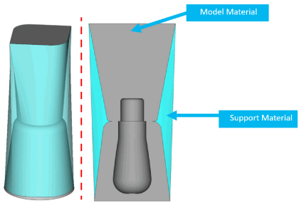
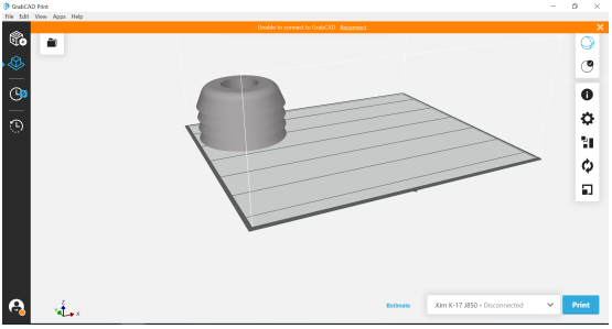
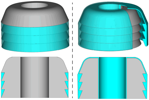
If the intention is to have a glossy finish, then the part should be sectioned, as shown in the figure below.
Figure 64: Positioning the bottle and cover on tray for glossy finish
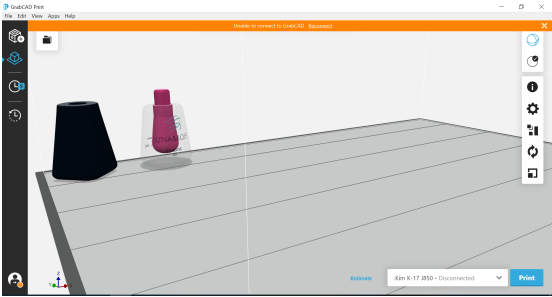
This results in no overhanging sections and a part with a glossy finish.
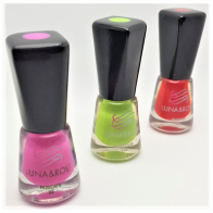
Figure 65: Prototypes of nail polish bottles in production
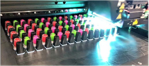
|
|
The parts in the above figure were printed on a J850 printer. |
Ghost Shelling for Reducing the Appearance of Layer Lines
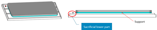
When printing flat, clear parts that have high surface finish requirements, layer lines may sometimes be visible on the bottom surface of the model that is closest to the build tray.
To improve print quality for these flat parts that are aligned on the build tray and to minimize the possibility of part curling, import your model as an assembly with a sacrificial part with a lower height, as shown below. This sacrificial part will rest on the build tray, forcing a higher bed of support to be laid down on-top of the pedestal.
Figure 66: Solution to minimize the appearance of layer lines
|
|
If these bodies are not imported as an assembly, GrabCAD Print automatically arranges them to be placed at the same height. |
Figure 67: Part with noticeable lines (left); part raised from tray with less noticeable lines (right)

|
|
The parts in the above figure were printed on a Connex3 printer. |
Ghost Shelling for Preventing a Matte Shadow
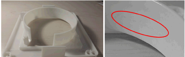
Sometimes, when printing parts with a glossy finish that contain surfaces with a slight draft angle, support material will be printed and cause an uneven surface finish that is a mix of matte and glossy.
Figure 68: Glossy printed part (left); uneven surface (right)
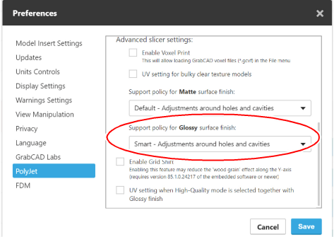
To minimize this effect:
•Enable the Smart support feature within GrabCAD Print.
Figure 69: GrabCAD Print Preferences > PolyJet > Advanced slicer settings screen
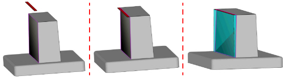
•Or, you can design a ghost shell in CAD/Magics to force the problematic surface to be printed completely in matte with the remainder of the model in glossy.
•Create a 0.1 mm shell the same size as the geometry to which you are trying to add support.
•Place this shell 0.3 mm above the area where you wish to the support to be applied.
•This ghost shell will ‘trick’ the printer into filling this area completely with support.
•This model material is so thin that it will be easily washed away during the support removal process.
Figure 70: Ghost shell (left); ghost shell in position (center); support material added (right)
Flexible Parts with Inner Core
PolyJet technology enables the creation of complex assemblies and parts with a range of materials and flexibilities. To fully harness these capabilities or to achieve a material property alternative to one of the preset digital material (DM) mixes, it is recommended to consider adding layered elements to your model. A different material will be assigned to each element to achieve a ‘hybrid’ mechanical property.
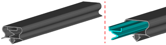
In the example below, refers to the design of a a refrigerator seal. Initially, it was printed in a few variations:
•Agilus30 White (shore 30 material)
•Agilus30 White and VeroWhite digital material, Shore 70
•VeroFlex White
However, the above variations, where the same material was assigned to the entire body, did not produce a realistic feeling of the part.
The digital material mix of Agilus30 and VeroWhite produced the required result. The solution was to create a model with two elements:
•A multi-material inner core, with Shore A 70
•An outer shell with Shore A 30
Figure 71: Refrigerator seal (left); Shore A 70 multi-material inner core with Shore A 30 outer shell (right)
GrabCAD Print has the ability to assign different material as a core/coating to a model and eliminate the need to model these as separate bodies on CAD.
Flexible Agilus30 for Reduced Tackiness
Parts printed with Tango or Agilus30 can be sticky once printed. One of the ways to reduce this stickiness is to design a shell of 0.1 mm around the part that is assigned a rigid material, such as VeroClear. This coating does not affect the Shore value, but it improves the feel of the part. This technique has been applied to the robotic soft gripper shown below.
Figure 72: Agilus30 robotic gripper (left); 0.1 mm VeroClear coating over Agilus30 core (right)
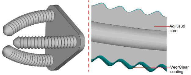
|
|
While coatings can be applied within GrabCAD Print, currently the thinnest coating that can be applied is 0.3 mm, which is typically not suitable for this application. |
There are many techniques to minimize the cost of producing parts additively. The well-known rule that complexity is free, may not always be the case, as a more complex part may require a larger support structure etc. Below we discuss several methods for reducing part cost:
•Time savings in the design phase
•Time savings in the printing phase
•Material usage reduction techniques where the design intent allows
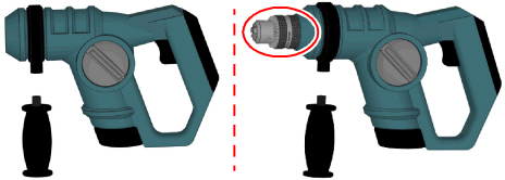
Explore the GrabCAD Community Library
The design process can be accelerated, and designs enhanced by importing pre-created components such as threads, nuts, bolts, hinges, bearings and clamps etc. from online repositories like the GrabCAD Community library.
Figure 73: GrabCAD community parts library (left); model added to design (right)
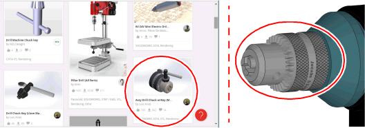
Figure 74: Before (left); after (right)
The scale tool within GrabCAD Print can be used to reduce the size of a model if it is used for concept verification, wind tunnel, etc. A cube that is 10x10x10 is double the volume of an 8x8x8 cube, so a small size reduction can have a large cost saving.
Figure 75: Rescaling results in a 50% reduction in volume
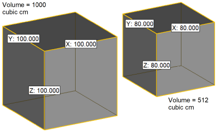
|
|
When using this technique make sure that wall/feature sizes are not too small to be printed or to fragile to be handled. |
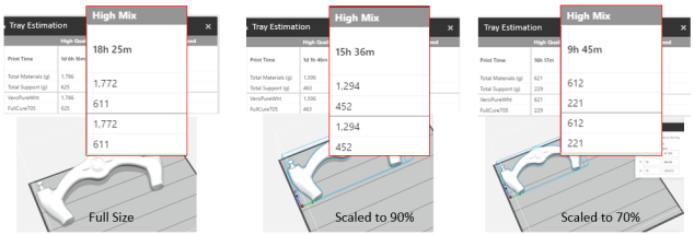
Here is a practical example of how scaling can be used to reduce print time and material costs
Figure 76: Concept game controller to be printed
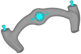
Figure 77: Time savings due to printing scaled models
|
|
These techniques may not be suitable for all applications and will need to be applied on a case by case basis. |
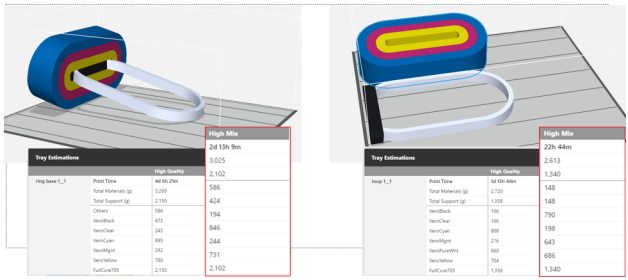
This example examines a LED desk lamp that if printed as designed, would take over two and half days to manufacture. If the lamp is sectioned, the model can be printed in less than one day and with reduced material costs. This is primarily due to the reduced height of the model that results in fewer printing passes.
Figure 78: Time savings due to sectioning models
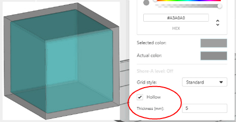
Creating hollow parts reduces the amount of model material used. This technique can be achieved during the design phase or in GrabCAD Print by selecting the hollow check box and defining a wall thickness.
|
|
Hollow is not available in VRML/OBJ texture based files. |
|
|
To ensure vibrant colors, wall thickness must be at least 2 mm. |
Figure 79: Hollow feature enabled
A range of hole light-weighting techniques and design optimizations can be applied to parts that are difficult to manufacture traditionally. And, although, these techniques do not affect printing time, they can significantly reduce material consumption, while still retaining the critical dimensions, features and strength of parts.
Figure 80: Original bracket
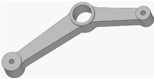
Figure 81: Different methods for creating a hollowed structure for the same part
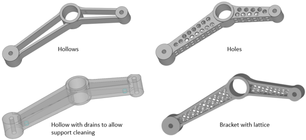
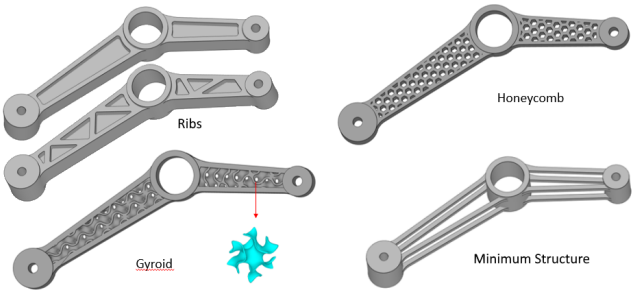
|
|
These techniques may not be suitable for all applications and will need to be applied on a case by case basis, taking the part’s end use requirements into consideration. |
Time savings can be achieved by changing the printing mode. With PolyJet technology, there are several printing modes. It is important to understand the differences between these modes as they enable different capabilities and print qualities. Additionally, changing between modes can be costly in terms of time, materials and calibration.
Stratasys J850 printers offer the following printing modes:
|
|
High Quality |
High Mix |
High Speed |
Super High Speed |
|
Layer Height |
14um |
27um |
27um |
54um |
|
Materials |
7 +Support |
7 + Support |
3 + Support |
1 + Support |
|
Speed |
0.5 X High Mix |
Standard |
2 x High Mix |
4 x High Mix |
In these printers the four printing heads are each split into two channels. This enables the printing of 8 materials simultaneously (7 model materials and one support material). This is the default printing mode. However, there is also the ability to link the two channels in each print head together enabling higher throughput (High Speed Mode), but this reduces the material options.
Below is an explanation of how this works in each of the printing modes.
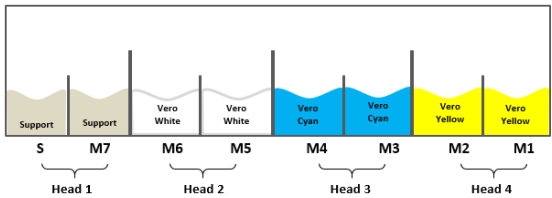
High Quality Mode/ High Mix Mode
In this mode, the print-head setup is the same for both printing modes. The layer height varies.
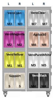
Figure 82: Seven material loaded in the print heads (sample)
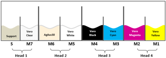
|
|
The materials loaded in the print heads can differ from the ones shown above. |
Figure 83: Material cabinet loaded for High Quality or High Mix modes (sample)
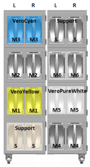
High Speed Mode
In this mode, printing is limited to three printing materials.
Figure 84: Three materials loaded in the print heads (sample)
|
|
The materials loaded in the print heads can differ from the ones shown above. |
Figure 85: Material cabinet loaded for High Speed mode (sample)
Super High Speed Mode
In this mode, printing is performed with a single material. Two print heads are dedicated to the support material and two to the model material:
Figure 86: DraftGrey loaded in the print heads
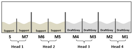
Figure 87: Material cabinet loaded for Super High Speed mode
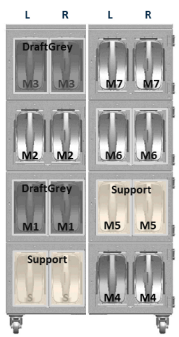
Optimal Material Cabinet Setup for J850 Printers
The following table describes the most efficient material cabinet setup when switching between High Quality/High Mix and Super High Speed.
Table 2: Efficient material loading recommendations
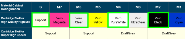
This setup minimizes the amount of waste material produced when switching back to full color from Super High Speed mode. The slots marked in green should be dedicated to these materials. The other slots are interchangeable.
Topology optimization is a design methodology that optimizes the designed part according to a finite element analysis (FEA) of expected loading conditions and forces to be applied to the part and the identification of critical features (bore size, mating surfaces etc.). Many CAD packages offer FEA as an overlay map that you can use as a guide to make design changes. Some packages will automatically redesign the part according to the results obtained from the FEA and the parameters that the user set.
This process creates parts that typically can only be produced using additive manufacture with a part optimized for material consumption and design intent.
The process typically follows these steps
•Import model to be optimized
•Define material
•Define no-go areas (The optimization is not applied to these areas.)
•Define constraints (fixed points)
•Apply loads
•Set optimization levels (amount of material to be reduced)
•Run optimization
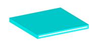
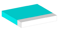
Figure 88: Model for optimization (left); no-go Areas (center); fixed points (right)
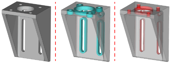
Figure 89: Forces applied (purple arrows) to the model in preparation for optimization
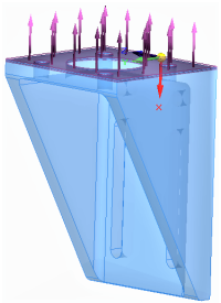
Figure 90: Setting optimization levels
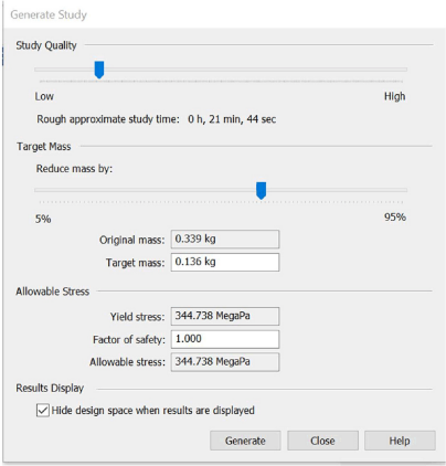
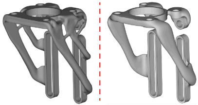
Figure 91: Optimizations results for materials with different mechanical properties
Considerations for Reproducing CMF Models
In the 2D printing industry color is achieved by printing on a white substrate (paper).In 3D printing similar processes are often employed. Additionally, PolyJet materials can appear slightly translucent in thin walled sections. These parts may be structurally sound and stable, but the color representation may be affected.
To achieve best color results, the recommended part thickness for various file types/color selection modes is a s follows:
•STL files - 2 mm
•Texture files (WRL/OBJ) - 3 mm
•Pantone - 6 mm
Table 3: Recommended minimum thickness for optimum color

|
STL Ensure a minimum thickness of 2 mm. |
|
WRL/OBJ Ensure a minimum thickness of 3 mm. •1 mm white core •1 mm surrounding color on each side |
|
Pantone Ensure a minimum thickness of 6 mm. •4 mm white core •1 mm surrounding color on each side Note: Pantone colors are validated for a thickness of 6 mm and above. |
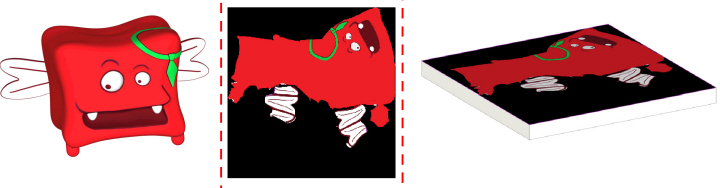
Before committing to large color critical prints, it is recommended to perform a sample print to ensure colors will be represented effectively. For checking Pantone, RGB, CMYK or Digital Material mixes, it is simple to apply the desired color to a sample geometry. However, when printing models with textures this can be challenging as tests of the model scaled down may still take substantial time to print and thin-walled sections may no longer accurately represent the designated color. In these situations, it is recommended to apply the texture file/s to a sample geometry to quickly and effectively validate the chosen color.
Figure 92: 3D Model (left); 2D texture (Center); texture applied to sample geometry (right)
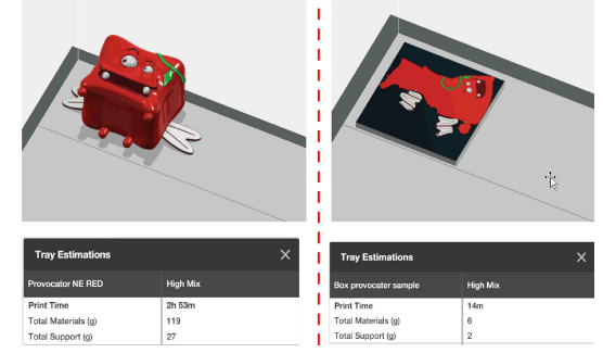
Printing time can be reduced considerably when printing a sample, as shown in the example below.
Figure 93: 3D Model tray estimation (left); sample geometry tray estimations (right)
With VeroVivid materials you can achieve the best color reproduction and accuracy. Pantone colors are only achievable when using the VeroVivid materials. The VeroVivid materials are transparent, however, by default, these materials are printed over a white core, resulting in vivid opaque colors.
Figure 94: VeroVivid color samples (top row); Vero color samples (bottom row)

If transparency is required, you can achieve it as follows:
•When using Vero and VeroVivid materials, by adding the VeroClear material to the part.
•When using VeroVivid materials, by disabling the assigned white core within GrabCAD Print.
The figure below shows transparency achieved with Vero versus transparency with VeroVivid materials.
Figure 95: Transparency with Vero and VeroClear (left); transparency with VeroVivid (right)
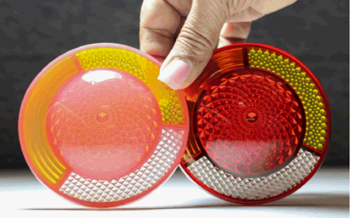
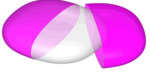
Along with the transparent effect, when using the VeroVivid materials, the depth of color is altered by part thickness. The thicker the part the darker the color.
Figure 96: Shapes printed with the same material and different thickness
This is not an issue when printing opaque parts, since the colors are applied as a uniform 1 mm coating onto a white core. Disabling this core within GrabCAD Print will assign the VeroVivid material throughout the part.
Depending on the thickness of the model or its geometry, this may result in unsatisfactory affects. To create a more uniform or lighter color effect, you can assign a coating layer within GrabCAD Print. This enables you to assign a model material of VeroClear and a coating of the desired VeroVivid color material. The coating thickness that can be applied within GrabCAD Print is between 0.3 mm to 3 mm. Coating thickness outside of this range needs to be created as part of the model's design.
Figure 97: Section of part designed with a 0.2 mm coating to be assigned VeroVivid Magenta on a VeroClear core
Images or graphics such as logos, text, pictures, and barcodes can be applied to models to help create photo-realistic models or represent detailed elements. When these elements are applied to a model, they are referred to as an image texture. The term ‘texture’ refers to an image or graphic and not necessarily a surface finish.
Most CAD packages do not support the output of texture files. Typically, this is achieved using specific design/animation software such as Autodesk® Maya®, or 3DS Max™. You can also achieve very impressive results using Adobe® Photoshop®, a more accessible software package with image editing tools that adjusts and edits the textures being applied. The output file can then be exported as an OBJ or WRL and sent to a pre-printing software like GrabCAD Print. More CAD packages are beginning to support the export of these file types. Solidworks® and Rhinoceros® (also know as Rhino o Rhino 3D) are some notable examples.
The overall process for applying a texture onto a 3D mesh involves mapping the texture (image, logo, decal etc.) directly onto the mesh before printing.
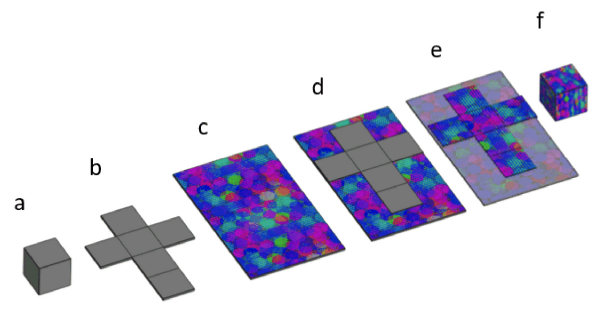
The main steps for applying texture are:
a. Design a 3D object, such as the cube shown below.
b. Map and unwrap the 3D object's geometry, so that it is represented in a 2D plane.
c. Import the 2D image texture.
d. Align the geometry map and texture image.
e. Overlay the texture image onto the part's geometry map. This process is called UV mapping.
(UV are coordinates found on the 2D image plane that are mapped to the 3D XYZ coordinates)
f. Use these mapped UV coordinates to wrap the 2D image onto the original 3D geometry.
In visual terms, the above process looks something like this:
Figure 98: UV mapping process
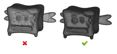
The quality and success of these textures is based on good UV mapping. As the UV map is directly related to the underlying mesh you should make sure that you have a high-quality mesh formed with triangles having similar edge lengths. This will help with enabling flexibly when positioning the texture and if mesh repair is needed later on.
Figure 99: Low quality mesh (left); high quality mesh (right)
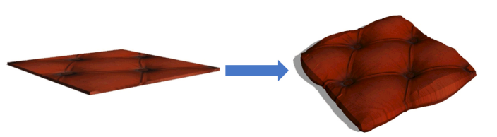
Bump maps create the illusion of height and topography by using light and shadow to trick your eye into thinking that the object has a more complex surface. In reality, the surface stays flat.
Displacement takes the render instructions provided by the bump map and turns it in to an actual change in mesh geometry.
Figure 100: Texture and bump map (left); texture with bump converted to displacement (right)
Bump/Height Maps
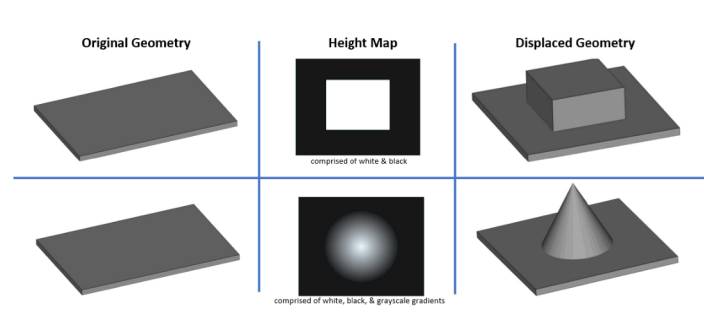
A bump/height map is an image comprised of white, black, and grays to dictate the height differences that need to be displayed.
•White = high points
•Black = low points
•Grayscale = gradients in between
A height map of just black and white will result in abrupt changes in geometry. Whereas, grayscale adds smoother transitions.
Figure 101: Height map and correlating displacement
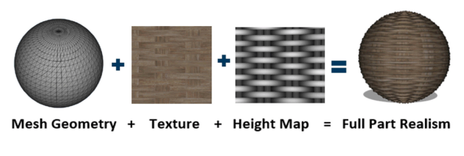
This bump/height map is saved as an image file, such as JPEG, IMG, and applied the same way as an image texture. Often these two images (both the texture and the height map) are used in conjunction to achieve fully realistic material effects.
Figure 102: Bump and texture maps applied to mesh
These bump/height maps were originally used to minimize model file size and increase processing speed for in-game animations. Programmers manipulated light and shadow to make models look realistic, while keeping their surface geometry unchanged, and therefore, easier and faster for the graphics engine to process.
Displacement
The process of changing this simulated bump geometry into an altered surface geometry is called displacement. Displacement converts a bump/height map that was applied as a texture to displace the mesh geometry to give it true highs and lows.
Figure 103: From simulated geometry to altered surface geometry
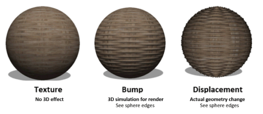
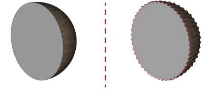
Figure 104: Before displacement (left); after displacement (right)
Typically, all that needs to be defined when converting bump to displacement is the severity of the displacement, that is, the difference in height between the black areas and the white areas of the map that will be applied during displacement.
Bump Considerations
It is important to ensure not only a dense mesh to provide geometry for a displacement, but also an even distribution of the polygons within the mesh.
Figure 105: Original model (left); after retopology (right)
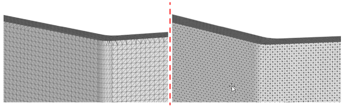
Figure 106: Original model displaced notice dense displacement at curve (left); retopologized model with displacement (right)
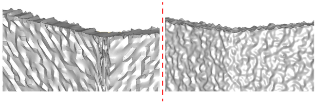
Models that have an uneven distribution should be retopologized either in the software they were designed in or in a 3rd party software, such as Instant Meshes™.
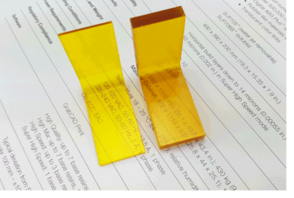
Models that contain a texture file, such as OBJ and WRL print the color designations as a
1 mm coating on a white core.
If the texture file has more than 1 pixel of transparency/alpha channel designated, the core is printed with VeroClear.
Figure 107: Globe model with a texture containing transparency printed on a clear core

Other Considerations for Files with a Texture Image
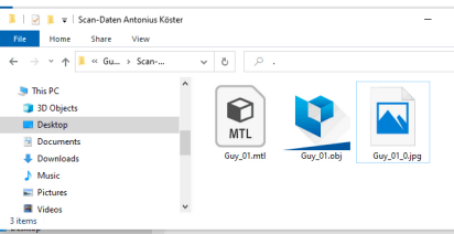
A WRL/OBJ file that has a texture applied will be saved with at least two files: the mesh file and the texture image (OBJ files will also contain a MTL material file). For the file to open correctly, the texture image (and .MTL file) must be in the same directory as the mesh file.
Figure 108: Mesh, texture image and material files in the same directory
Multiple Overlapping Non-Joined Shells
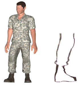
Many design packages create models that were never designed to exist in the real world and are for on-screen visualization, examples include game characters. These models may be comprised of multiple open shells that do not necessarily join together. When these models are printed, errors can occur with support placement causing models to separate.
Figure 109: Figurine (left); section view of leg showing 3 separate open shells ankle, boot and trousers (right)
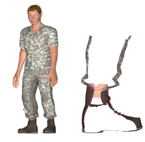
Figure 110: Figurine after shrink wrap operation (left); section view of leg comprised of a single shell (right)
Another effect of multiple overlapping shells can be potential color bleeding from darker underlying shells onto lighter colored external surfaces.
Figure 111: Overlapping shell of 1 mm under white surface (left); transparency applied to view the internal structure (right)
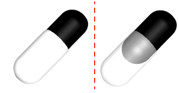
Figure 112: Printed part showing color bleeding from underlying area
For optimum results, ensure that models are watertight before exporting. Techniques to try depending on the software package include:
•Merge shells
•Shrink wrap part
•Convert textures to texture atlas
It is common practice in many design software packages to design parts with a low polygon count or resolution, additional detail is applied through rendering.
It is impossible to print files with a higher resolution than the underlying mesh, any facets or polygons visible in the model will be transferred to the printed part.
Figure 113: Rendered model (left); underlying mesh model (right)
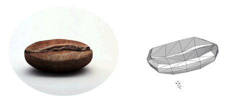
Ensure the model has a high enough polygon count to ensure satisfactory quality when printing. Try applying polygon subdivision or smoothing operations.
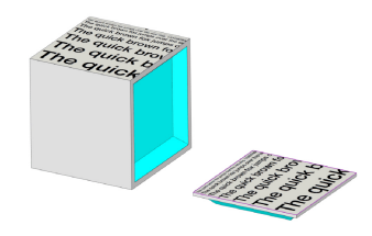
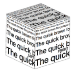
When applying text to a part via a texture, consider the part orientation, as the printing process can affect the sharpness, clarity and legibility of fine print text and detailed labels.
In the example below, text appears on each side of the cube.
Figure 114: Cube with text on the all sides
When printed, the best print quality is as follows:
1.Top surface
2.Front and back surfaces
3.Left and right surfaces
Figure 115: Best quality when printed
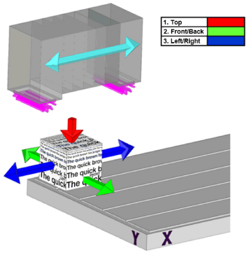
To ensure optimum quality of text and details, prefer splitting the model, and orienting the text elements on the tray so that they are printed facing upward. After printing, the separated parts can be assembled.
Figure 116: Cube side separated and facing upward