About the F120 Printer
The Stratasys F120 3D printer incorporates the latest in innovative technology to provide you with precise 3D-printed parts from a CAD design. Stratasys’ Fused Deposition Modeling (FDM) technology provides accurate parts, including internal features, which can be used to field-test form, fit, and function. Direct Digital Manufacturing (DDM) allows for the creation of customized end-use parts straight from 3D CAD data. The F120 printer features a servo/belt driven XY gantry with multiple modeling material capability.
•The F120 Printer
•Welcome Kit (containing documentation on how to download your user guide and common tools for maintaining the printer)
•GrabCAD Print Software Package
•A Computer Workstation (not sold by Stratasys, for preparing build files)
•Maximum build area of 10 x 10 x 10 inch (254 x 254 x 254 mm)
•Touchscreen Graphical User Interface
•Wi-Fi capabilities
•Two front USB ports
•Camera for remote monitoring
This guide provides information for selecting an appropriate location for the F120 printer. This guide also provides instructions for unpacking and preliminary set-up. Information of particular importance is presented in one of three formats:
|
|
A Warning: indicates a procedure that may cause injury to an operator if the procedure is not followed. |

|
|
A Caution: indicates a procedure that may cause damage to equipment if the procedure is not followed. |

|
|
A NOTE is used to highlight a specific point or to provide an operational tip. While useful, a NOTE does not indicate a procedure that can cause injury or damage if it is not followed. |

Decide where to install the printer based on the following:
1.Space Requirements
2.Environmental Requirements
3.Electrical Requirements
4.LAN Requirements
|
|
The F120 printers are capable of generating vibrations depending mainly on part build geometry and material characteristics. This consideration will need to be taken into account if locating the printer near vibration sensitive equipment. |
Physical Specifications and Space Requirements
Make sure that the installation site floor space can accommodate the printer’s weight and dimensions, plus required clearances. The installation location must be a flat level surface that is stable and capable of holding 500 pounds (227 kg).
|
|
Caution: |
|
|
If a table is used to support the printer, the recommended height is 30 inches ± 3 inches (76 cm ± 7.6cm) and it should be capable of holding 500 pounds (227 kg). If the table has casters, they must be lockable. |
|
Description |
Weight |
Dimensions |
|---|---|---|
|
Printer Crated |
350 pounds (159 kg) |
Width: 48 inches (122 cm) Depth: 40 inches (102 cm) Height: 42.75 inches (109 cm) |
|
Printer Uncrated |
295 pounds (134 kg) |
Width: 34 inches (86 cm) Depth: 28 inches (71 cm) Height: 36 inches (92 cm) |
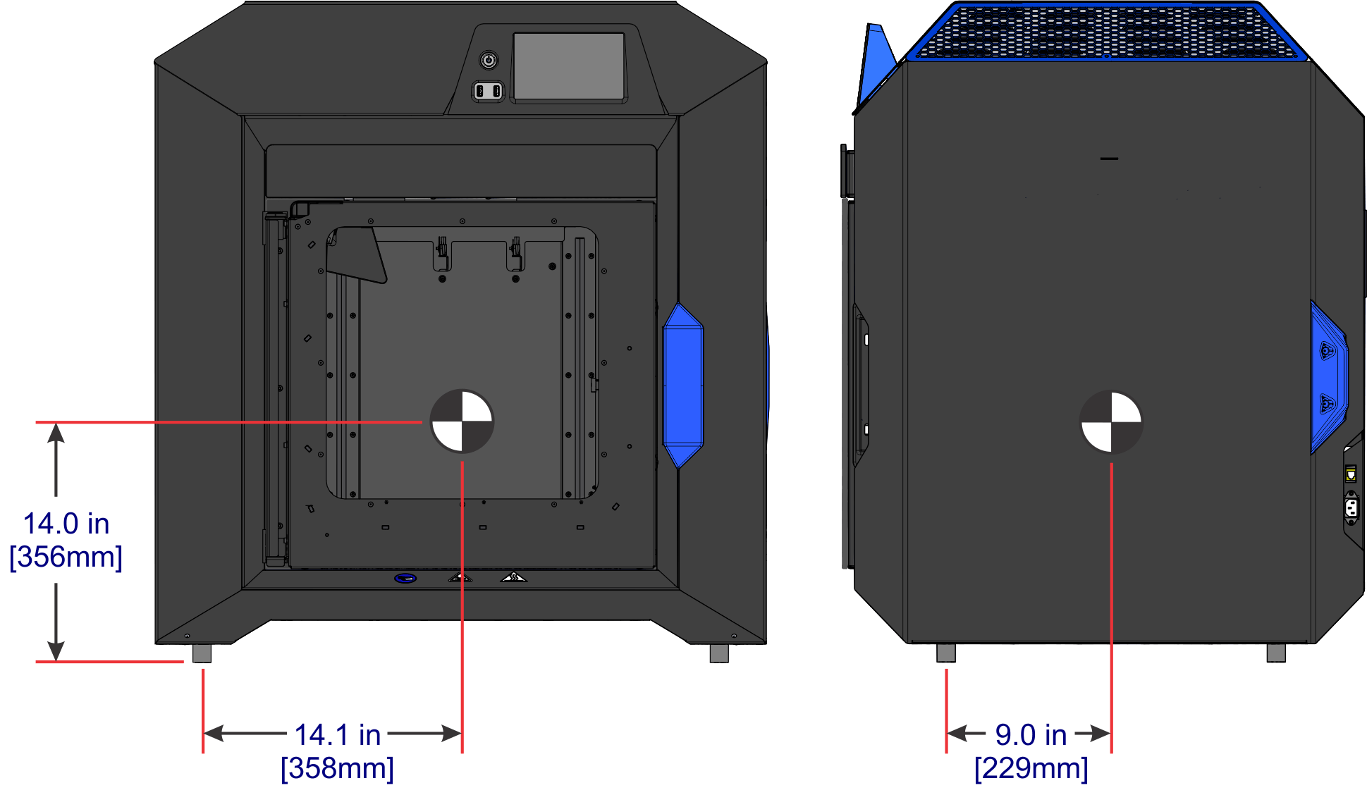
Figure 1: F120 Center of Mass
|
|
The center of mass dimensions shown are taken from the bottom center of the front left foot. |
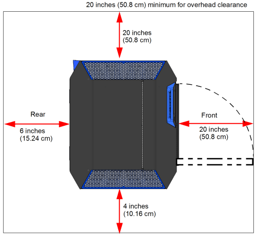
Minimum Operational Clearances
Sufficient rear and side clearances allow for proper air circulation, while sufficient front clearance allows enough room for the oven door and drawers to be opened.
|
Right Side Clearance |
Minimum 20 inches (50.8 cm) |
|
Left Side Clearance |
Minimum 4 inches (10.16 cm) |
|
Rear Clearance |
Minimum 6 inches (15.24 cm) |
|
Front Clearance |
Minimum 20 inches (50.8 cm) |
|
Overhead Clearance |
Minimum 20 inches (50.8 cm) |
Figure 2: Minimum Clearances
•The F120 printer can be used in any controlled environment.
•Air quality conditions with excessive solid particulates (conductive or non-conductive) may result in system damage.
•Air quality conditions in which airborne oils are allowed to accumulate on or within the printer can damage the plastic components.
•System operating temperature shall be in the range of 59°F to 86°F (15°C to 30°C), with relative humidity range of 30% to 70% non-condensing.
•System storage temperature shall be in the range of 32°F to 95°F (0°C to 35°C), with relative humidity range of 20% to 90% non-condensing.
•Altitude shall not exceed 6561.68 feet (2000 m).
•Material storage shall be in the range of 55°F to 86°F (13°C to 30°C), with relative humidity less than 70%.
•Noise emission (acoustic):
•<32dBA when idle
•<46dBA when building
Heat Output
Heat dissipation occurs mostly through the top of the printer. Heat output is material dependent due to the various temperatures maintained in the build chamber.
|
Material Type |
Heat Output (while building) |
Heat Output (while idle) |
|---|---|---|
|
ABS |
~2300 BTU/hr |
~1800 BTU/hr |
|
ASA |
~2300 BTU/hr |
~1800 BTU/hr |
Power Consumption
Power consumption is material dependent due to the various temperatures maintained in the build chamber.
|
Material Type |
Power Consumption |
Power Consumption |
Power Consumption |
|---|---|---|---|
|
ABS |
650 W |
510 W |
10 W |
|
ASA |
650 W |
510 W |
10 W |
AC Power Requirements
•50/60 Hz.
•Voltage: 100-132, 200-240 VAC.
•Current: 15/7A.
•The grounded electrical outlet must connect to either a Euro or a US power cord plug (provided in the Welcome Kit) and must be located within 2 m (80 inches) of the printer.
|
|
Caution: A power cable is provided for connecting the printer to the AC electric source. Do not use it with other equipment. |
Operation of the printer outside this range is not recommended; degradation of performance and shortened component life expectancy will be experienced. Facilities who are unsure of their power quality should contact their service provider.
|
|
Caution: Do not use an extension cord or power strip; doing so can result in intermittent power issues. Connect the power cord directly into the receptacle. |
For GrabCAD Print workstation requirements please visit:
http://help.grabcad.com/article/195-system-requirements-for-grabcad-print.
While on the GrabCAD website, be sure to join the F120 GrabCAD community.
If utilizing a LAN connection for communication and file transfer functions, the LAN connection is a 100 base T, Ethernet protocol, RJ45 connector. One 15 foot (4.57 m) CAT6, 10/100 base T cable is supplied with the printer, located in the Welcome Kit. The printer will function in either DHCP or Static IP configurations.
A LAN connection is not required however, as the printer is also capable of file transfer via a Wi-Fi connection or a USB flash drive plugged into either of the printer’s USB ports. See the F120 User Guide for detailed information and instructions on transferring files to the printer.
Before opening the shipping crate, inspect the crate for signs of exterior damage.
Report evidence of excessive damage to Stratasys and the shipping company.
•Utility knife
•A pallet jack or forklift may be required to move the system.
•Cutter for cable ties
Unpacking and Positioning the Printer
|
|
Make sure that there is at least 70 inches (178 cm) of clearance for the printer before you begin the process of unpacking the printer. |
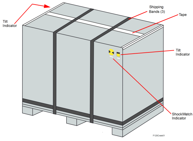
1.Inspect the Tilt Indicators (2) and ShockWatch indicator affixed to the exterior of the cardboard box. If possible, take a picture of these indicators to share with your installation representative. If damage is detected upon installation, this photo will assist your installation representative in determining the cause of damage (Figure 3).
Figure 3: Shipping Crate Detail (Back View)
|
|
Warning: Personal Injury Hazard Shipping bands are very tight; when cutting shipping bands they may pop open with force. Wear safety glasses when removing the shipping bands. |
2.Carefully cut the shipping bands (3) and remove the tape (Figure 3).
3.Lift and remove the protective cardboard container panel encasing the printer (Figure 4).
Figure 4: Removing the cardboard
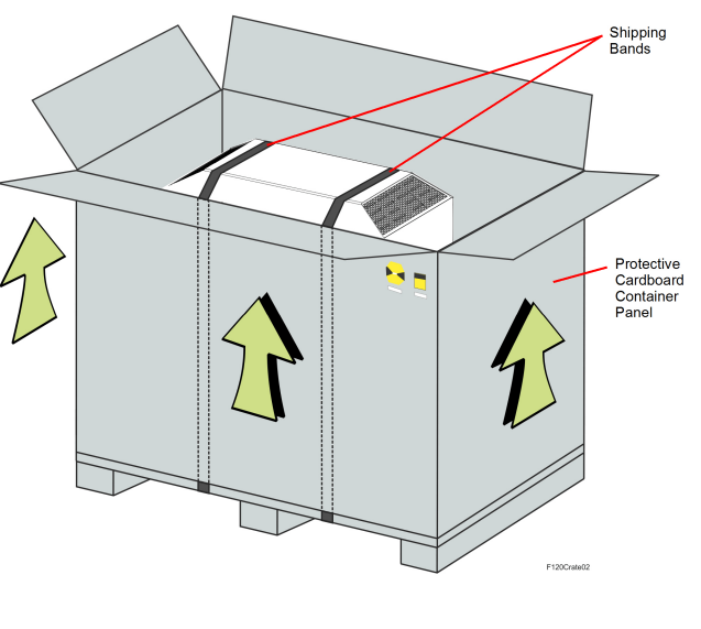
4.Carefully cut the shipping bands that secure the printer to the pallet (Figure 4). Remove the bands and protective foam pads.
5.Remove all tape and carefully unwrap the printer by pulling the plastic bag downward.
|
|
Caution: Use care when cutting the plastic bag to avoid scratching the printer’s surfaces. |
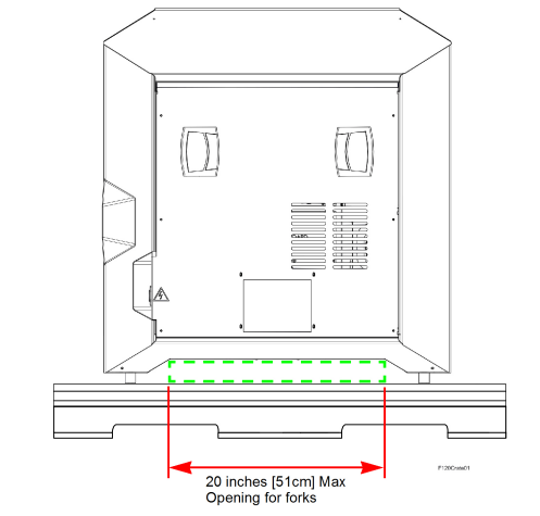
6.Using a utility knife, cut away and remove the plastic bag’s material ensuring that the bag is not blocking the fork lift opening or the printer’s feet (Figure 5).
7.Remove the protective film from the touchscreen and the logos on the printer’s exterior.
8.Inspect the printer’s exterior for dents and scratches. Immediately report any damage to Stratasys and the shipping company.
9.Using a forklift, carefully raise the printer vertically and remove the shipping base.
|
|
Caution: Access the fork lift opening beneath the printer, between the feet (Figure 5). |
10.Move the printer into its approximate operating location and gently lower it until it rests on its feet.
|
|
Position the printer to allow at least three feet of clearance on all sides until the installation process is complete, see “Physical Specifications and Space Requirements” (page 2). Refer to Chapter 2 of the F120 User Guide for final setup instructions. |
11.Open the oven door, cut the cable tie securing the startup materials, and remove the startup materials from the oven chamber.
12.Remove the orange tape securing the tip wipe assemblies to the purge chute.
13.Open the top cover. Remove the orange clip affixed to the X belt, and cut the orange tie wrap securing the X motor to the printer’s frame (front-left corner of frame).
Electrical Installation Requirements
•A dedicated outlet of 100-132, 200-240 VAC~15-7A 50/60 Hz has been installed.
•The grounded electrical outlet is within 2 meters (80 inches) of the printer.
•The grounded electrical outlet is able to accept either a Euro or US power cord plug.
•If utilizing a LAN connection, the LAN connection is within 4 meters (14 feet) of the printer.
•The site’s environmental temperature is between 59°F to 86°F (13°C to 30°C).
•The site’s environmental humidity is between 30% to 70%, non-condensing.
•The site’s altitude does not exceed 6561.68 feet (2000 m).
•GrabCAD Print software has been downloaded and installed on the user’s workstation PC.
•The Welcome Kit and build trays have been removed from the oven chamber.
•The orange clip securing the X belt in place has been removed.
•The orange tie wrap securing the X motor in place has been removed.